Flex pcb vibration
Understanding Flex PCB Vibration: Causes and Effects
Flex PCBs, or flexible printed circuit boards, have become increasingly prevalent in modern electronics due to their versatility, lightweight nature, and ability to conform to various shapes. However, one critical aspect that engineers and designers must consider is the vibration that these flexible circuits may encounter during their operational lifespan. Understanding the causes and effects of flex PCB vibration is essential for ensuring the reliability and longevity of electronic devices.
To begin with, it is important to recognize that vibrations can originate from multiple sources.
These sources can be external, such as environmental factors like mechanical shocks, or internal, such as the operation of motors and other moving components within a device. Regardless of the origin, vibrations can induce mechanical stress on the flex PCB, potentially leading to a range of issues.
One primary cause of flex PCB vibration is the mechanical resonance that occurs when the frequency of external vibrations matches the natural frequency of the PCB.
This resonance can amplify the vibrations, causing significant mechanical deformation. Over time, repeated exposure to such conditions can lead to fatigue and eventual failure of the PCB material. Additionally, the solder joints and interconnections on the flex PCB are particularly susceptible to damage from vibrations, as they can develop cracks or become detached, leading to intermittent or complete loss of electrical connectivity.
Moreover, the effects of flex PCB vibration are not limited to mechanical damage alone.
Vibrations can also impact the electrical performance of the circuit. For instance, vibrations can cause variations in the impedance of the conductive traces, leading to signal integrity issues. This is particularly critical in high-frequency applications where even minor impedance changes can result in significant signal degradation. Furthermore, vibrations can induce noise and electromagnetic interference (EMI), which can disrupt the normal operation of the electronic device.
To mitigate the adverse effects of flex PCB vibration, several strategies can be employed.
One effective approach is to design the flex PCB with appropriate mechanical support and damping materials. These materials can absorb and dissipate the vibrational energy, reducing the mechanical stress on the PCB. Additionally, optimizing the layout and routing of the conductive traces can help minimize the impact of vibrations on signal integrity. For example, using wider traces and maintaining consistent trace widths can reduce impedance variations.
Another important consideration is the selection of materials for the flex PCB.
High-quality materials with superior mechanical properties, such as polyimide, can enhance the durability and resilience of the PCB against vibrations. Furthermore, advanced manufacturing techniques, such as laser drilling and precision etching, can improve the accuracy and reliability of the flex PCB, reducing the likelihood of defects that could be exacerbated by vibrations.
In conclusion, understanding the causes and effects of flex PCB vibration is crucial for the successful design and deployment of electronic devices. By recognizing the potential sources of vibration and implementing appropriate mitigation strategies, engineers can enhance the reliability and performance of flex PCBs. This, in turn, ensures that electronic devices can withstand the rigors of their operational environments, providing consistent and dependable performance over their intended lifespan.

Design Strategies to Minimize Flex PCB Vibration
Flex PCBs, or flexible printed circuit boards, are increasingly utilized in various applications due to their adaptability, lightweight nature, and ability to conform to complex geometries. However, one of the challenges associated with flex PCBs is their susceptibility to vibration, which can lead to mechanical failures and compromised performance. To address this issue, it is essential to implement design strategies that minimize flex PCB vibration, ensuring reliability and longevity in demanding environments.
To begin with, material selection plays a crucial role in mitigating vibration.
Choosing materials with high tensile strength and flexibility can significantly reduce the impact of vibrational forces. Polyimide, for instance, is a popular choice due to its excellent mechanical properties and thermal stability. Additionally, incorporating a thicker copper layer can enhance the structural integrity of the flex PCB, providing better resistance to vibrational stress.
Another effective strategy involves optimizing the layout and routing of the flex PCB.
By strategically placing components and traces, designers can distribute the mechanical load more evenly across the board. This can be achieved by avoiding sharp bends and ensuring smooth, gradual curves in the flex regions. Furthermore, maintaining a consistent trace width and spacing can help prevent stress concentration points, which are prone to vibration-induced damage.
Moreover, the use of stiffeners can be instrumental in reducing flex PCB vibration.
Stiffeners are rigid materials, such as FR4 or stainless steel, that are bonded to specific areas of the flex PCB to provide additional support. By reinforcing critical sections, stiffeners can help maintain the board’s shape and reduce the amplitude of vibrations. It is important to carefully select the placement and size of stiffeners to avoid adding unnecessary weight or compromising the flexibility of the PCB.
In addition to these design considerations, implementing proper mounting techniques can further minimize vibration.
Securely fastening the flex PCB to the enclosure or chassis can prevent excessive movement and reduce the risk of mechanical failure. Using vibration-damping materials, such as rubber grommets or foam pads, can also absorb and dissipate vibrational energy, protecting the flex PCB from harmful oscillations.
Thermal management is another critical aspect to consider when designing flex PCBs for vibration-prone environments.
Excessive heat can exacerbate the effects of vibration, leading to material fatigue and failure. Therefore, incorporating effective thermal management solutions, such as heat sinks or thermal vias, can help maintain optimal operating temperatures and enhance the overall durability of the flex PCB.
Furthermore, conducting thorough testing and analysis during the design phase is essential to identify potential vibration issues.
Finite element analysis (FEA) can simulate the mechanical behavior of the flex PCB under various vibrational conditions, allowing designers to make informed decisions and optimize the design accordingly. Additionally, vibration testing, such as random vibration or sine sweep tests, can validate the performance of the flex PCB and ensure it meets the required specifications.
In conclusion, minimizing flex PCB vibration requires a comprehensive approach that encompasses material selection, layout optimization, stiffener implementation, proper mounting techniques, thermal management, and rigorous testing. By carefully considering these factors, designers can enhance the reliability and performance of flex PCBs in vibration-prone environments, ensuring their successful integration into a wide range of applications.

Testing Methods for Flex PCB Vibration Resistance
Testing methods for flex PCB vibration resistance are crucial in ensuring the reliability and longevity of flexible printed circuit boards (PCBs) in various applications. These methods are designed to simulate the conditions that flex PCBs might encounter in real-world environments, thereby identifying potential weaknesses and ensuring that the boards can withstand the stresses of vibration. To achieve this, several testing techniques are employed, each with its own set of procedures and objectives.
One of the primary methods used to test flex PCB vibration resistance is the sine vibration test.
This test involves subjecting the PCB to sinusoidal vibrations at different frequencies and amplitudes. The purpose of this test is to identify the resonant frequencies of the PCB, which are the frequencies at which the board experiences maximum displacement. By understanding these resonant frequencies, engineers can design the PCB to avoid operating at these critical points, thereby reducing the risk of failure due to vibration.
In addition to sine vibration testing, random vibration testing is also commonly used.
Unlike sine vibration testing, which uses a single frequency at a time, random vibration testing subjects the PCB to a broad spectrum of frequencies simultaneously. This method is more representative of real-world conditions, where vibrations are rarely limited to a single frequency. Random vibration testing helps to identify potential failure points that might not be apparent under sine vibration testing, providing a more comprehensive assessment of the PCB’s vibration resistance.
Another important testing method is the shock test, which evaluates the PCB’s ability to withstand sudden, high-magnitude impacts.
During a shock test, the PCB is subjected to a series of controlled impacts, simulating conditions such as drops or collisions. This test is particularly important for applications where the PCB might be exposed to sudden shocks, such as in automotive or aerospace environments. By assessing the PCB’s performance under these conditions, engineers can ensure that the board will remain functional even after experiencing significant impacts.
Thermal cycling tests are also essential in evaluating the vibration resistance of flex PCBs.
These tests involve subjecting the PCB to repeated cycles of heating and cooling, simulating the thermal stresses that the board might encounter in its operating environment. Thermal cycling can cause materials to expand and contract, potentially leading to mechanical fatigue and failure. By combining thermal cycling with vibration testing, engineers can assess how these combined stresses affect the PCB’s performance, providing a more accurate representation of real-world conditions.
Furthermore, finite element analysis (FEA) is a valuable tool in the testing process.
FEA is a computer-based simulation technique that allows engineers to model the PCB and predict its behavior under various conditions. By using FEA, engineers can identify potential failure points and optimize the design of the PCB before physical testing begins. This not only saves time and resources but also helps to ensure that the final product is as robust as possible.
In conclusion, testing methods for flex PCB vibration resistance are essential in ensuring the reliability and durability of these critical components. By employing a combination of sine vibration testing, random vibration testing, shock testing, thermal cycling, and finite element analysis, engineers can thoroughly evaluate the performance of flex PCBs under a variety of conditions. These testing methods provide valuable insights into the potential weaknesses of the PCB, allowing for design improvements and ultimately ensuring that the final product can withstand the rigors of its intended application.
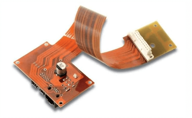
Material Selection for Enhanced Flex PCB Vibration Durability
When designing flexible printed circuit boards (flex PCBs) for applications where vibration is a significant concern, material selection becomes a critical factor in ensuring durability and performance.
Flex PCBs are increasingly used in various industries, including automotive, aerospace, and consumer electronics, due to their ability to bend and conform to complex shapes. However, their inherent flexibility also makes them susceptible to mechanical stresses, particularly vibrations, which can lead to premature failure if not properly addressed.
To enhance the vibration durability of flex PCBs, it is essential to consider the mechanical properties of the materials used in their construction.
The base material, typically a polyimide film, plays a pivotal role in determining the overall flexibility and resilience of the PCB. Polyimide is favored for its excellent thermal stability, chemical resistance, and mechanical strength. However, not all polyimide films are created equal; variations in thickness, tensile strength, and elongation at break can significantly impact the flex PCB’s ability to withstand vibrational forces.
In addition to the base material, the choice of adhesive is equally important.
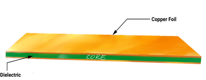
The adhesive layer bonds the copper foil to the polyimide substrate, and its properties can influence the flex PCB’s mechanical performance. High-performance adhesives that offer strong adhesion, flexibility, and resistance to thermal cycling are preferred. These adhesives help maintain the integrity of the copper-polyimide bond under repeated flexing and vibration, thereby reducing the risk of delamination and electrical failure.
Moreover, the copper foil itself must be carefully selected to enhance vibration durability.
Rolled annealed (RA) copper is often chosen over electro-deposited (ED) copper for flex PCBs due to its superior ductility and fatigue resistance. RA copper can endure repeated bending and flexing without cracking, making it more suitable for applications where the PCB will be subjected to continuous mechanical stress. Additionally, the thickness of the copper foil should be optimized to balance electrical performance with mechanical robustness.
Another critical aspect to consider is the overall design and layout of the flex PCB.
Strategic placement of components and traces can mitigate the effects of vibration. For instance, avoiding sharp bends and ensuring smooth transitions in the circuit layout can reduce stress concentrations that may lead to mechanical failure. Furthermore, incorporating strain relief features, such as fillets and teardrops at trace-to-pad junctions, can distribute mechanical stress more evenly and enhance the PCB’s durability.
The use of protective coatings and encapsulants can also contribute to improved vibration resistance.
Conformal coatings, such as silicone or polyurethane, provide an additional layer of protection against environmental factors and mechanical stress. These coatings can absorb some of the vibrational energy, thereby reducing the direct impact on the flex PCB. Encapsulation, on the other hand, involves embedding the entire PCB in a protective material, which can offer superior protection but may limit flexibility.
In conclusion, enhancing the vibration durability of flex PCBs requires a comprehensive approach that involves careful material selection, thoughtful design, and the use of protective measures. By choosing the right combination of polyimide films, adhesives, copper foils, and protective coatings, engineers can significantly improve the resilience of flex PCBs in vibration-prone environments. This holistic approach ensures that flex PCBs can maintain their performance and reliability, even under challenging mechanical conditions, thereby extending their operational lifespan and reducing the risk of failure in critical applications.

