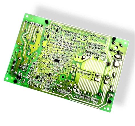
Pcb gerber file
Understanding The Basics Of PCB Gerber Files
Printed Circuit Boards (PCBs) are the backbone of modern electronic devices, serving as the foundation upon which electronic components are mounted and interconnected. To manufacture a PCB, one must first create a detailed design that specifies the layout of the board. This design is then translated into a format that can be understood by PCB fabrication machines. This is where Gerber files come into play. Understanding the basics of PCB Gerber files is crucial for anyone involved in electronics design and manufacturing.
Gerber files are a standard file format used to describe the printed circuit board images: copper layers, solder mask, legend, and other essential elements
. Named after the Gerber Scientific Instrument Company, these files have become the industry standard for PCB manufacturing. They are essentially a set of vector image files that provide precise instructions to the fabrication machines on how to create the physical board.
To begin with, it is important to recognize that a single PCB design is typically represented by multiple Gerber files.
Each file corresponds to a different layer or aspect of the PCB. For instance, there will be separate files for the top copper layer, bottom copper layer, solder mask layers, and silkscreen layers. This separation ensures that each aspect of the PCB is accurately represented and can be individually processed during manufacturing.
Transitioning to the technical details, Gerber files use a coordinate system to define the shapes and locations of various features on the PCB.
The files contain commands that instruct the fabrication machines on how to draw lines, arcs, and other shapes. These commands are based on the X and Y coordinates, which specify the exact positions on the board. Additionally, Gerber files can include information about apertures, which are the shapes and sizes of the tools used to create the features on the PCB.
Moreover, it is essential to understand the two main types of Gerber formats: RS-274D and RS-274X.
The older RS-274D format requires a separate aperture file to define the shapes and sizes of the tools, whereas the more modern RS-274X format includes this information within the Gerber file itself. The RS-274X format is more commonly used today due to its simplicity and reduced risk of errors.
In addition to the Gerber files, PCB manufacturing also requires a drill file, typically in the Excellon format.
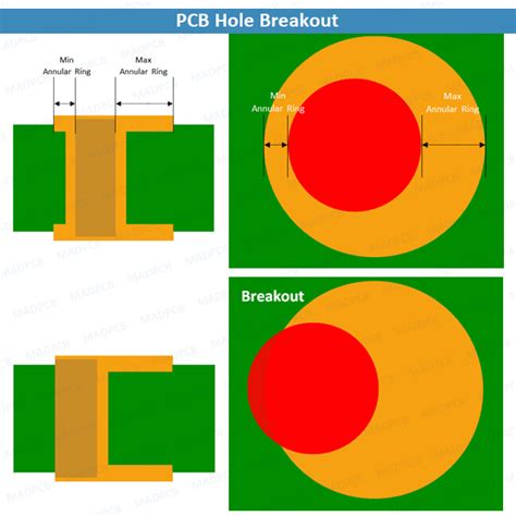
This file specifies the locations and sizes of the holes to be drilled in the PCB, such as those for vias and component leads. The drill file works in conjunction with the Gerber files to ensure that the final PCB meets the design specifications.
Furthermore, it is important to verify the Gerber files before sending them to the manufacturer.
This process, known as Design Rule Checking (DRC), involves using specialized software to check for errors and ensure that the files comply with the design rules and manufacturing capabilities. By catching potential issues early, DRC helps prevent costly mistakes and delays in the manufacturing process.
In conclusion, Gerber files are an indispensable part of PCB design and manufacturing. They provide a standardized way to communicate the intricate details of a PCB design to the fabrication machines, ensuring that the final product matches the designer’s intent. By understanding the basics of Gerber files, including their structure, formats, and verification processes, designers can create accurate and manufacturable PCBs, ultimately contributing to the successful development of electronic devices.
How To Generate Gerber Files For Your PCB Design
Generating Gerber files for your PCB design is a crucial step in the manufacturing process, as these files serve as the blueprint for fabricating the printed circuit board. To begin with, it is essential to understand that Gerber files are a standard format used to describe the various layers of a PCB, including copper layers, solder mask, silkscreen, and drill data. These files are universally accepted by PCB manufacturers, making them indispensable for ensuring that your design is accurately translated into a physical board.
The first step in generating Gerber files is to complete your PCB design using a CAD (Computer-Aided Design) software
. Popular CAD tools such as Altium Designer, Eagle, KiCad, and OrCAD offer comprehensive features for designing PCBs. Once your design is finalized, you need to prepare it for export. This involves verifying that all components are correctly placed, traces are appropriately routed, and design rules are adhered to. It is advisable to run a Design Rule Check (DRC) to identify and rectify any potential issues that could affect the manufacturability of the PCB.
After ensuring that your design is error-free, the next step is to configure the layers that need to be exported.
Typically, a PCB design consists of multiple layers, including top and bottom copper layers, solder mask layers, silkscreen layers, and mechanical layers. Each of these layers must be exported as a separate Gerber file. In your CAD software, navigate to the export or plot section, where you will find options to select the layers you wish to include in the Gerber files. It is crucial to name each file appropriately to avoid any confusion during the manufacturing process.
In addition to the Gerber files, you will also need to generate a drill file, which provides information about the locations and sizes of holes to be drilled on the PCB.
This file is typically in the Excellon format and is essential for the accurate placement of vias and component leads. Ensure that the drill file is correctly aligned with the Gerber files to prevent any discrepancies during fabrication.
Once you have configured the layers and drill file, proceed to export the Gerber files.
Most CAD tools offer a straightforward process for this, often involving a single click to generate all necessary files. However, it is important to review the generated files using a Gerber viewer. This step allows you to visually inspect each layer and verify that the files accurately represent your design. Any errors detected at this stage can be corrected before sending the files to the manufacturer.
Finally, when you are confident that the Gerber files are accurate, package them into a single compressed folder, typically in ZIP format.
This folder should include all the Gerber files, the drill file, and any additional documentation that the manufacturer might require, such as a readme file or assembly drawings. Providing clear and detailed information helps the manufacturer understand your design requirements and reduces the likelihood of errors during production.
In conclusion, generating Gerber files for your PCB design involves a series of meticulous steps, from finalizing the design in CAD software to exporting and verifying the files. By following these steps diligently, you can ensure that your PCB design is accurately translated into a physical board, ready for manufacturing.

Common Mistakes To Avoid When Creating Gerber Files
Creating Gerber files is a critical step in the process of designing printed circuit boards (PCBs). These files serve as the blueprint for manufacturing the PCB, containing all the necessary information about the board’s layout, including the copper layers, solder mask, and silkscreen. However, even experienced designers can make mistakes that can lead to costly errors or delays in production. To ensure a smooth manufacturing process, it is essential to be aware of common mistakes and take steps to avoid them.
One frequent error is the incorrect assignment of layer names.
Gerber files rely on precise naming conventions to distinguish between different layers of the PCB. Misnaming a layer can result in confusion during the manufacturing process, potentially leading to incorrect fabrication. To prevent this, always double-check that each layer is correctly named according to industry standards and the specific requirements of your manufacturer.
Another common mistake is failing to include all necessary files.
A complete set of Gerber files typically includes files for each copper layer, solder mask, silkscreen, and drill data. Omitting any of these files can cause significant issues during production. To avoid this, create a checklist of all required files and verify that each one is present before submitting your design to the manufacturer.
In addition to missing files, incorrect drill file formats can also pose problems.
Drill files, often provided in Excellon format, must be compatible with the manufacturer’s equipment. Using an incorrect format can lead to misaligned or improperly sized holes, which can compromise the functionality of the PCB. To mitigate this risk, consult with your manufacturer to ensure that your drill files are in the correct format and include all necessary information, such as tool sizes and hole locations.
Moreover, insufficient clearances between traces and pads can lead to short circuits or other electrical issues.
It is crucial to adhere to the design rules specified by your manufacturer, which typically include minimum clearance requirements. Utilizing design rule checks (DRCs) within your PCB design software can help identify and rectify any clearance issues before generating the Gerber files.
Another pitfall to avoid is neglecting to include a board outline.
The board outline defines the physical dimensions and shape of the PCB, and its absence can result in manufacturing errors or delays. Ensure that the board outline is clearly defined in a separate layer and that it accurately represents the intended dimensions of the PCB.
Furthermore, it is essential to verify the accuracy of your Gerber files through a thorough review process.
Many PCB design software packages offer built-in Gerber viewers that allow you to inspect each layer visually. Taking the time to review your files can help identify any discrepancies or errors that may have been overlooked during the design phase.
Lastly, communication with your manufacturer is paramount. Providing clear and detailed fabrication notes can help prevent misunderstandings and ensure that your design is manufactured correctly. These notes should include information about layer stack-up, material specifications, and any special requirements or instructions.
In conclusion, creating Gerber files is a meticulous process that requires attention to detail and adherence to best practices. By avoiding common mistakes such as incorrect layer naming, missing files, improper drill formats, insufficient clearances, and lack of a board outline, you can significantly reduce the risk of errors during manufacturing. Additionally, thorough file reviews and clear communication with your manufacturer are essential steps to ensure a successful PCB production. By being vigilant and methodical, you can create accurate Gerber files that facilitate a smooth and efficient manufacturing process.

Best Practices For Reviewing And Verifying Gerber Files
When working with printed circuit boards (PCBs), ensuring the accuracy and integrity of Gerber files is paramount. Gerber files serve as the blueprint for PCB manufacturing, containing all the necessary information about the board’s layout, including copper layers, solder masks, and silkscreens. Therefore, meticulous review and verification of these files are essential to avoid costly errors and ensure a smooth manufacturing process.
To begin with, it is crucial to use reliable Gerber file viewers.
These specialized software tools allow you to visualize the layers and components of your PCB design. By examining each layer individually, you can identify potential issues such as misaligned traces, incorrect pad sizes, or missing elements. Additionally, these viewers often provide features like measurement tools and DRC (Design Rule Check) capabilities, which can further aid in the verification process.
Transitioning to the next step, it is important to cross-reference the Gerber files with the original design files.
This involves comparing the exported Gerber files against the design files from your PCB design software. By doing so, you can ensure that no data was lost or altered during the export process. Pay close attention to critical aspects such as trace widths, spacing, and component placements. Any discrepancies between the design files and the Gerber files should be addressed promptly to prevent manufacturing defects.
Furthermore, it is advisable to perform a thorough inspection of the drill filesDrill files, often included with Gerber files, specify the locations and sizes of holes on the PCB. Verifying these files is essential to ensure that all vias, mounting holes, and component lead holes are correctly positioned and sized. Inaccurate drill files can lead to misaligned components or even render the PCB unusable. Therefore, double-checking these files against the design specifications is a crucial step in the review process.
In addition to visual inspections, employing automated verification tools can significantly enhance the accuracy of your review.
These tools can perform comprehensive checks on your Gerber files, identifying potential issues that may not be immediately apparent through manual inspection. For instance, they can detect violations of design rules, such as minimum trace widths or spacing, and flag potential manufacturing problems like acid traps or solder bridging. Utilizing these tools can save time and reduce the risk of errors, ultimately leading to a more reliable PCB design.
Moreover, it is essential to communicate effectively with your PCB manufacturer.
Providing them with clear and detailed documentation, including a comprehensive Bill of Materials (BOM) and assembly drawings, can help ensure that your design is accurately interpreted and manufactured. Additionally, maintaining an open line of communication with the manufacturer allows for prompt resolution of any issues that may arise during the production process. This collaborative approach can help mitigate potential problems and ensure a successful outcome.
Finally, conducting a final review before submitting your Gerber files for manufacturing is a best practice that should not be overlooked.
This review should encompass all aspects of the design, including layer stack-up, trace routing, and component placement. Taking the time to perform this final check can help catch any last-minute errors or oversights, providing an additional layer of assurance that your PCB design is ready for production.
In conclusion, reviewing and verifying Gerber files is a critical step in the PCB design process. By utilizing reliable tools, cross-referencing design files, inspecting drill files, employing automated verification, communicating effectively with manufacturers, and conducting a final review, you can ensure the accuracy and integrity of your Gerber files. These best practices not only help prevent costly errors but also contribute to the successful manufacturing of high-quality PCBs.


