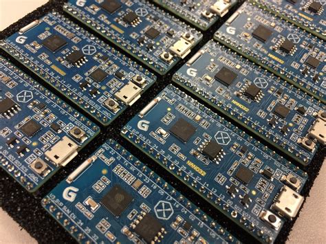
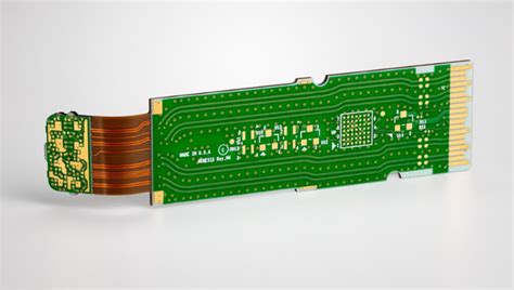
High speed signals in pcb
Designing High-Speed PCB Traces for Signal Integrity
Designing high-speed PCB traces for signal integrity is a critical aspect of modern electronics engineering. As the demand for faster and more efficient electronic devices continues to grow, ensuring that high-speed signals maintain their integrity throughout a printed circuit board (PCB) becomes increasingly important. The challenges associated with high-speed signal transmission are numerous, but with careful design considerations, these challenges can be effectively managed.
One of the primary concerns in high-speed PCB design is minimizing signal loss and distortion.
Signal integrity can be compromised by various factors, including impedance mismatches, crosstalk, and electromagnetic interference (EMI). To address these issues, it is essential to maintain consistent impedance along the signal traces. This can be achieved by carefully controlling the trace width, spacing, and the dielectric properties of the PCB material. Impedance matching ensures that the signal travels smoothly without reflections, which can cause data corruption and signal degradation.
In addition to impedance control, managing crosstalk is crucial for high-speed signal integrity.
Crosstalk occurs when a signal in one trace induces unwanted noise in an adjacent trace. To mitigate crosstalk, designers can increase the spacing between high-speed traces or use ground planes to shield the signals. Ground planes not only help in reducing crosstalk but also provide a return path for the signals, which is essential for maintaining signal integrity. Furthermore, differential signaling, where two complementary signals are transmitted on a pair of traces, can be employed to reduce the effects of crosstalk and EMI.
Another important consideration in high-speed PCB design is the layout of the traces.
The length and routing of the traces can significantly impact signal integrity. It is advisable to keep high-speed traces as short and direct as possible to minimize signal delay and attenuation. When longer traces are unavoidable, techniques such as serpentine routing can be used to match the lengths of differential pairs, ensuring that the signals arrive simultaneously at their destination. Additionally, avoiding sharp bends and right-angle turns in the traces can prevent signal reflections and maintain signal integrity.
The choice of PCB materials also plays a vital role in high-speed signal integrity.
High-frequency signals are more susceptible to losses caused by the dielectric properties of the PCB substrate. Materials with low dielectric constant and low loss tangent are preferred for high-speed applications. These materials help in reducing signal attenuation and maintaining signal integrity over longer distances. Moreover, the use of advanced PCB fabrication techniques, such as microvias and buried vias, can further enhance signal integrity by minimizing the parasitic inductance and capacitance associated with traditional through-hole vias.
Thermal management is another aspect that cannot be overlooked in high-speed PCB design.
High-speed signals generate more heat, which can affect the performance and reliability of the PCB. Proper thermal management techniques, such as the use of thermal vias, heat sinks, and adequate ventilation, are essential to dissipate heat and maintain the integrity of high-speed signals.
In conclusion, designing high-speed PCB traces for signal integrity requires a comprehensive understanding of various factors that can affect signal transmission. By carefully controlling impedance, managing crosstalk, optimizing trace layout, selecting appropriate materials, and implementing effective thermal management, designers can ensure that high-speed signals maintain their integrity throughout the PCB. As technology continues to advance, the importance of meticulous high-speed PCB design will only grow, making it a critical area of focus for electronics engineers.
Techniques for Minimizing Crosstalk in High-Speed PCB Layouts
In the realm of high-speed printed circuit board (PCB) design, crosstalk is a critical issue that can significantly degrade signal integrity and overall system performance. Crosstalk occurs when a signal transmitted on one trace inadvertently induces an undesired signal on an adjacent trace. As data rates increase and signal rise times become faster, the potential for crosstalk escalates, necessitating meticulous design techniques to mitigate its effects. Several strategies can be employed to minimize crosstalk in high-speed PCB layouts, ensuring reliable and efficient signal transmission.
One fundamental technique to reduce crosstalk is to maintain adequate spacing between signal traces.
By increasing the distance between adjacent traces, the electromagnetic coupling that causes crosstalk is diminished. This approach is particularly effective in high-speed designs where traces are densely packed. However, it is essential to balance trace spacing with the overall board real estate to avoid excessive PCB size.
Another effective method is to implement proper trace routing practices.
Routing high-speed signals on different layers, separated by a ground plane, can significantly reduce crosstalk. The ground plane acts as a shield, absorbing and dissipating the electromagnetic interference that would otherwise couple into adjacent traces. Additionally, routing high-speed signals orthogonally on adjacent layers can further minimize crosstalk by reducing parallelism between traces.
Utilizing differential signaling is another powerful technique to combat crosstalk.
Differential pairs consist of two complementary signals that are routed together, with one signal being the inverse of the other. This configuration inherently cancels out common-mode noise, including crosstalk, as the induced noise affects both signals equally but in opposite directions. Consequently, the differential receiver can effectively reject the noise, preserving signal integrity.
Grounding and power distribution also play a crucial role in minimizing crosstalk.
Ensuring a low-impedance return path for high-speed signals is vital. A well-designed ground plane provides a continuous and low-inductance return path, reducing the potential for crosstalk. Additionally, decoupling capacitors should be strategically placed near high-speed components to stabilize the power supply and further mitigate noise.
Shielding is another technique that can be employed to reduce crosstalk.
By enclosing critical signal traces in a grounded shield, the electromagnetic interference is contained, preventing it from coupling into adjacent traces. This approach is particularly useful in scenarios where high-speed signals must traverse long distances or pass through noisy environments.
Moreover, careful consideration of via placement is essential in high-speed PCB design.
Vias introduce discontinuities in the signal path, which can exacerbate crosstalk. Minimizing the number of vias and ensuring they are properly back-drilled can help maintain signal integrity. Additionally, placing ground vias adjacent to signal vias can provide a return path for the signal, reducing the potential for crosstalk.
Simulation and analysis tools are invaluable in the design process, allowing engineers to model and predict crosstalk behavior before physical implementation.
By leveraging these tools, designers can identify potential crosstalk issues and optimize the PCB layout accordingly. Iterative simulations and adjustments can lead to a robust design that minimizes crosstalk and ensures reliable high-speed signal transmission.
In conclusion, minimizing crosstalk in high-speed PCB layouts requires a multifaceted approach that encompasses trace spacing, routing practices, differential signaling, grounding, shielding, via placement, and simulation. By meticulously applying these techniques, designers can achieve high-performance PCB designs that maintain signal integrity and meet the stringent demands of modern high-speed applications.
The Role of Ground Planes in High-Speed PCB Design
In the realm of high-speed printed circuit board (PCB) design, the role of ground planes cannot be overstated. As electronic devices continue to evolve, the demand for faster data transmission rates has led to the necessity of high-speed signals. These signals, however, bring with them a host of challenges, including signal integrity issues, electromagnetic interference (EMI), and crosstalk. Ground planes play a crucial role in mitigating these challenges, ensuring the reliable performance of high-speed PCBs.
To begin with, ground planes serve as a reference point for all signals on the PCB.
This is particularly important in high-speed designs where even minor variations in signal reference can lead to significant issues. By providing a consistent reference, ground planes help maintain signal integrity, ensuring that signals are transmitted accurately and without distortion. This is achieved by minimizing the loop area through which the signal current flows, thereby reducing the inductance and potential for noise.
Moreover, ground planes are instrumental in controlling EMI.
High-speed signals can generate significant electromagnetic fields, which can interfere with other components on the PCB or even with external devices. A well-designed ground plane acts as a shield, absorbing and dissipating these electromagnetic fields. This shielding effect is enhanced when the ground plane is placed close to the signal traces, as it helps to contain the electromagnetic fields within a confined space, thereby reducing the potential for interference.
In addition to controlling EMI, ground planes also play a vital role in reducing crosstalk.
Crosstalk occurs when a signal in one trace induces an unwanted signal in an adjacent trace, leading to potential data corruption. By providing a low-impedance path for the return current, ground planes help to minimize the coupling between adjacent traces. This is particularly important in high-density designs where traces are placed in close proximity to each other. The presence of a continuous ground plane ensures that the return current follows the path of least impedance, thereby reducing the likelihood of crosstalk.
Furthermore, ground planes contribute to the overall thermal management of the PCB.
High-speed signals often result in increased power dissipation, which can lead to thermal issues if not properly managed. Ground planes, with their large surface area, act as heat sinks, dissipating heat away from critical components and preventing localized hotspots. This not only enhances the reliability of the PCB but also extends the lifespan of the components.
It is also worth noting that the placement and design of ground planes require careful consideration.
For instance, splitting ground planes can lead to potential issues if not done correctly. A split ground plane can create a discontinuity in the return path, leading to increased impedance and potential signal integrity issues. Therefore, it is essential to ensure that any splits in the ground plane are carefully planned and that return paths are maintained.
In conclusion, ground planes are an indispensable element in high-speed PCB design. They provide a stable reference point for signals, control EMI, reduce crosstalk, and aid in thermal management. As the demand for higher data transmission rates continues to grow, the importance of ground planes in ensuring the reliable performance of high-speed PCBs will only become more pronounced. By understanding and effectively implementing ground planes, designers can overcome the challenges associated with high-speed signals and achieve optimal performance in their PCB designs.
Understanding Signal Reflection and Termination in High-Speed PCBs
In the realm of high-speed printed circuit boards (PCBs), understanding signal reflection and termination is paramount to ensuring optimal performance and reliability. As electronic devices continue to evolve, the demand for faster data transmission rates has led to the proliferation of high-speed signals within PCBs. These signals, characterized by rapid voltage transitions, can introduce a host of challenges, including signal reflection, which can significantly degrade signal integrity if not properly managed.
Signal reflection occurs when a transmitted signal encounters an impedance discontinuity along its transmission path.
This discontinuity can arise from various sources, such as changes in trace width, vias, connectors, or even the PCB material itself. When a signal reflects, it travels back towards the source, potentially interfering with the original signal and causing distortions. These distortions can manifest as ringing, overshoot, or undershoot, all of which can compromise the integrity of the data being transmitted.
To mitigate the adverse effects of signal reflection, proper termination techniques must be employed.
Termination involves matching the impedance of the transmission line to the source and load impedances, thereby minimizing reflections. There are several termination methods commonly used in high-speed PCB design, each with its own advantages and considerations.
One widely used termination method is series termination, where a resistor is placed in series with the signal line near the source.
This resistor helps to match the source impedance with the characteristic impedance of the transmission line, thereby reducing reflections. Series termination is particularly effective for point-to-point connections and is relatively simple to implement. However, it may not be suitable for multi-drop configurations, where multiple receivers are connected to a single transmission line.
Another common technique is parallel termination, which involves placing a resistor at the end of the transmission line, typically between the signal line and ground.
This method ensures that the impedance at the end of the line matches the characteristic impedance, thereby absorbing any reflected signals. Parallel termination is effective for both point-to-point and multi-drop configurations, but it can increase power consumption due to the continuous current flow through the termination resistor.
The Thevenin termination method combines elements of both series and parallel termination.
It involves placing a voltage divider network at the end of the transmission line, which matches the impedance and provides a stable reference voltage. This method is particularly useful for differential signaling, where maintaining a balanced impedance is crucial for minimizing reflections and ensuring signal integrity.
In addition to these termination techniques, careful PCB layout practices are essential for managing high-speed signals.
Ensuring consistent trace impedance, minimizing via usage, and maintaining proper spacing between signal lines can all contribute to reducing impedance discontinuities and reflections. Furthermore, the use of controlled impedance traces, where the trace width and spacing are precisely defined, can help maintain signal integrity across the entire transmission path.
In conclusion, understanding signal reflection and termination is critical for the successful design of high-speed PCBs. By employing appropriate termination techniques and adhering to best practices in PCB layout, designers can effectively mitigate the adverse effects of signal reflection, ensuring reliable and high-performance data transmission. As the demand for faster and more efficient electronic devices continues to grow, mastering these concepts will remain a fundamental aspect of high-speed PCB design.