Pcb prototype the easy way
Understanding The Basics Of PCB Prototyping
Printed Circuit Board (PCB) prototyping is a crucial step in the development of electronic devices, serving as a bridge between the initial design and the final product. Understanding the basics of PCB prototyping is essential for engineers and hobbyists alike, as it allows for the testing and refinement of circuit designs before mass production. This process not only helps in identifying potential design flaws but also provides an opportunity to evaluate the functionality and performance of the circuit in a real-world setting.
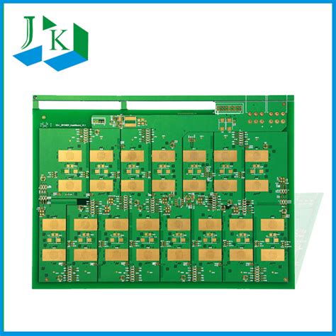
To begin with, PCB prototyping involves creating a preliminary version of a circuit board to test its design.
This is typically done after the schematic design phase, where the electronic components and their connections are laid out. The prototype serves as a physical representation of the design, allowing for hands-on testing and troubleshooting. It is important to note that the prototyping phase is iterative, often requiring multiple versions to achieve the desired outcome. This iterative nature underscores the importance of flexibility and adaptability in the design process.
One of the key aspects of PCB prototyping is the choice of materials and manufacturing techniques.
The most common material used for PCBs is FR-4, a composite material made of woven fiberglass cloth with an epoxy resin binder. This material is favored for its durability, thermal resistance, and cost-effectiveness. However, depending on the specific requirements of the project, other materials such as polyimide or metal-core PCBs may be used. The choice of material can significantly impact the performance and cost of the prototype, making it a critical consideration in the prototyping process.
In addition to material selection, the manufacturing technique plays a vital role in PCB prototyping.
Traditional methods such as etching and drilling have been largely supplanted by more advanced techniques like CNC milling and 3D printing. These modern methods offer greater precision and speed, allowing for rapid prototyping and quick iterations. Furthermore, advancements in software tools have made it easier to design and simulate PCB layouts, reducing the likelihood of errors and improving the overall efficiency of the prototyping process.
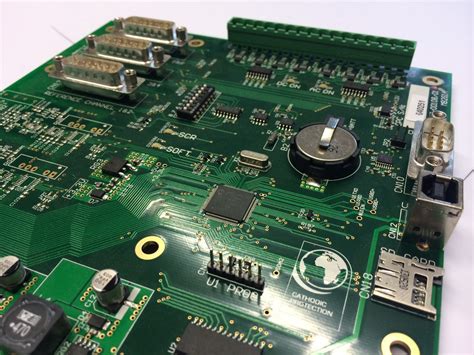
Another important factor in PCB prototyping is the testing and validation of the prototype.
Once the prototype is manufactured, it undergoes a series of tests to ensure that it meets the design specifications and functions as intended. This may include electrical testing to verify connectivity and signal integrity, as well as environmental testing to assess the prototype’s performance under various conditions. The feedback obtained from these tests is invaluable, guiding further refinements and adjustments to the design.
Moreover, collaboration and communication are essential components of successful PCB prototyping.
Engaging with a team of engineers, designers, and manufacturers can provide diverse perspectives and insights, leading to more innovative and effective solutions. Additionally, clear communication of design requirements and constraints can help streamline the prototyping process, minimizing delays and reducing costs.
In conclusion, understanding the basics of PCB prototyping is fundamental to the development of reliable and efficient electronic devices. By carefully considering material selection, manufacturing techniques, and testing procedures, designers can create prototypes that accurately reflect their design intentions. Furthermore, embracing collaboration and communication can enhance the prototyping process, ultimately leading to a successful transition from prototype to production. As technology continues to evolve, the methods and tools available for PCB prototyping will undoubtedly advance, offering even greater opportunities for innovation and improvement in the field of electronics.
Step-By-Step Guide To Easy PCB Design
Designing a printed circuit board (PCB) can seem daunting, especially for beginners. However, with the right approach and tools, creating a PCB prototype can be a straightforward and rewarding process. The first step in this journey is to clearly define the requirements of your project. Understanding the functionality, size constraints, and components needed will provide a solid foundation for your design. Once you have a clear vision, the next step is to choose the appropriate software. There are numerous PCB design tools available, ranging from beginner-friendly options like Fritzing to more advanced software such as Eagle or KiCad. Selecting the right tool depends on your level of expertise and the complexity of your project.
After selecting your design software, the next phase involves creating a schematic.
This is a crucial step where you map out the electrical connections between components. It is essential to ensure that each component is correctly represented and that all connections are accurately depicted. This schematic will serve as the blueprint for your PCB layout. As you work on the schematic, it is beneficial to double-check connections and component values to prevent errors later in the process. Once the schematic is complete, you can proceed to the layout design.
Transitioning from the schematic to the layout involves placing components on the board and routing the electrical connections.
This step requires careful consideration of component placement to optimize space and ensure efficient routing. It is advisable to place components logically, grouping related parts together to minimize trace lengths and reduce potential interference. Additionally, paying attention to design rules, such as trace width and spacing, is crucial to ensure the board functions correctly and reliably.
As you refine the layout, it is important to consider the board’s physical constraints, such as size and shape.
This is particularly relevant if the PCB needs to fit within a specific enclosure or if there are thermal management considerations. Once the layout is satisfactory, running a design rule check (DRC) is a prudent step. This automated process will identify any violations of the design rules, allowing you to address potential issues before proceeding to fabrication.
With the layout finalized, the next step is to generate the necessary files for manufacturing.
These typically include Gerber files, which provide detailed information about each layer of the PCB, and a bill of materials (BOM) listing all components required for assembly. It is essential to review these files carefully to ensure accuracy, as any errors at this stage can lead to costly manufacturing mistakes.
Finally, selecting a reliable PCB manufacturer is crucial to bringing your design to life.
Many manufacturers offer prototyping services with quick turnaround times, allowing you to test and iterate on your design efficiently. When choosing a manufacturer, consider factors such as cost, lead time, and the quality of their work. Once the prototype is received, thorough testing is necessary to verify that the PCB functions as intended. This may involve checking electrical connections, testing signal integrity, and ensuring that all components operate correctly.
In conclusion, while designing a PCB prototype may initially seem complex, following a structured approach can simplify the process significantly. By carefully planning each step, from schematic creation to layout design and manufacturing, you can create a functional and reliable PCB prototype with ease.

Top Tools For Simplifying PCB Prototyping
In the rapidly evolving world of electronics, the demand for efficient and streamlined processes in printed circuit board (PCB) prototyping has never been higher. As engineers and hobbyists alike seek to bring their innovative designs to life, the need for tools that simplify the PCB prototyping process becomes paramount. Fortunately, advancements in technology have led to the development of a variety of tools that cater to this need, making PCB prototyping more accessible and less time-consuming.
To begin with, computer-aided design (CAD) software plays a crucial role in simplifying PCB prototyping.
These software tools allow designers to create detailed schematics and layouts with precision and ease. Among the most popular CAD tools is Eagle, known for its user-friendly interface and extensive library of components. Eagle’s integration with other platforms and its ability to handle complex designs make it a favorite among both beginners and seasoned professionals. Similarly, KiCad, an open-source alternative, offers a comprehensive suite of features that rival those of commercial software, providing a cost-effective solution without compromising on functionality.
Transitioning from design to physical prototype, PCB fabrication services have emerged as indispensable tools in the prototyping process.
Companies such as JLCPCB and PCBWay offer rapid prototyping services that allow designers to upload their designs and receive fabricated boards in a matter of days. These services not only save time but also reduce the potential for errors that can occur during manual fabrication. By leveraging these services, designers can focus on refining their designs rather than getting bogged down in the intricacies of board production.
In addition to fabrication services, prototyping platforms like Arduino and Raspberry Pi have revolutionized the way designers approach PCB prototyping.
These platforms provide a versatile and cost-effective means of testing and iterating on designs before committing to a final product. With a wide array of shields and modules available, designers can quickly assemble and test their circuits, making adjustments as needed without the need for a custom PCB at every iteration. This flexibility is particularly beneficial for those working on complex projects that require multiple iterations to perfect.
Furthermore, simulation tools have become an integral part of the PCB prototyping process.
Tools such as LTSpice and Proteus allow designers to simulate their circuits in a virtual environment, identifying potential issues before they manifest in the physical prototype. By using these tools, designers can optimize their circuits for performance and reliability, ensuring that the final product meets the desired specifications. This not only saves time but also reduces costs associated with reworking faulty designs.
Finally, online communities and resources have become invaluable tools for those engaged in PCB prototyping.
Platforms like GitHub and forums such as the EEVblog provide a wealth of knowledge and support, enabling designers to learn from the experiences of others and share their own insights. These communities foster collaboration and innovation, helping to drive the field of PCB prototyping forward.
In conclusion, the landscape of PCB prototyping has been transformed by a suite of tools that simplify the process from design to production. By leveraging CAD software, fabrication services, prototyping platforms, simulation tools, and online resources, designers can navigate the complexities of PCB prototyping with greater ease and efficiency. As technology continues to advance, these tools will undoubtedly evolve, further streamlining the path from concept to reality.
Common Mistakes To Avoid In PCB Prototyping
In the realm of electronics design, creating a printed circuit board (PCB) prototype is a crucial step that can significantly influence the success of a project. However, the process is fraught with potential pitfalls that can lead to costly errors and delays. Understanding common mistakes in PCB prototyping and how to avoid them is essential for both novice and experienced designers.
One of the most frequent errors is inadequate planning.
Before diving into the design phase, it is imperative to have a clear understanding of the project requirements, including the functionality, size constraints, and environmental conditions the PCB will face. Failing to define these parameters can lead to a design that does not meet the necessary specifications, resulting in a need for costly redesigns.
Transitioning from planning to design, another common mistake is neglecting to consider the layout and routing of the PCB.
Poor layout decisions can lead to issues such as signal interference, inadequate power distribution, and thermal management problems. To mitigate these risks, designers should prioritize a logical component placement and ensure that traces are routed efficiently. Utilizing design software with simulation capabilities can help identify potential issues before the prototype is manufactured. Furthermore, it is crucial to adhere to design for manufacturability (DFM) guidelines, which can vary depending on the manufacturing process and the capabilities of the chosen fabrication partner.
In addition to layout concerns, overlooking the importance of component selection can also lead to significant setbacks.
Selecting components without considering their availability, lead times, and compatibility with the rest of the design can result in delays and increased costs. It is advisable to work closely with suppliers to ensure that components are readily available and to consider alternative parts that can be used if necessary. Moreover, designers should be mindful of the tolerances and specifications of each component to ensure they function correctly within the circuit.
As the design progresses, another area where mistakes frequently occur is in the documentation process.
Incomplete or inaccurate documentation can lead to misunderstandings and errors during the manufacturing phase. It is essential to provide comprehensive documentation, including schematics, bill of materials (BOM), and assembly instructions. This documentation should be reviewed and updated regularly to reflect any changes made during the design process. Clear communication with the manufacturing partner is also vital to ensure that the prototype is produced accurately and efficiently.
Once the prototype is manufactured, testing and validation are critical steps that should not be overlooked.
A common mistake is to assume that the prototype will function as intended without thorough testing. Rigorous testing should be conducted to verify that the PCB meets all design specifications and performs reliably under expected operating conditions. This process may involve functional testing, environmental testing, and compliance testing, depending on the application.
In conclusion, while PCB prototyping can be a complex and challenging process, being aware of common mistakes and taking proactive steps to avoid them can lead to a more successful outcome. By prioritizing careful planning, thoughtful design, meticulous documentation, and thorough testing, designers can streamline the prototyping process and increase the likelihood of achieving a functional and reliable PCB. As technology continues to evolve, staying informed about best practices and emerging trends in PCB design will further enhance the ability to create effective prototypes with ease.