Iphone 7 pcb file
Understanding The Design: A Deep Dive Into The iPhone 7 PCB File
The iPhone 7, released by Apple in 2016, marked a significant evolution in smartphone technology, not only in terms of user experience but also in its internal architecture. At the heart of this architecture lies the Printed Circuit Board (PCB), a critical component that orchestrates the device’s functionality. Understanding the design of the iPhone 7 PCB file offers valuable insights into the intricate engineering that powers this iconic device.
To begin with, the PCB serves as the backbone of the iPhone 7, housing and interconnecting various electronic components.
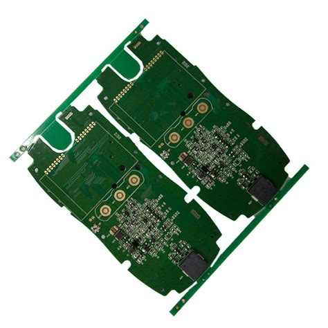
It is a multi-layered board, meticulously designed to accommodate the complex circuitry required for the phone’s operations. The design of the PCB file is a testament to Apple’s commitment to innovation and efficiency. Each layer of the PCB is dedicated to specific functions, such as power distribution, signal routing, and grounding, ensuring optimal performance and minimal interference.
Transitioning to the layout of the PCB, it is essential to note that the iPhone 7’s design prioritizes space efficiency.
The compact arrangement of components is achieved through advanced techniques such as surface-mount technology (SMT), which allows components to be mounted directly onto the surface of the board. This approach not only saves space but also enhances the reliability of connections, reducing the likelihood of mechanical failures. Furthermore, the use of high-density interconnect (HDI) technology enables the integration of more components within a limited area, a crucial factor in maintaining the sleek form factor of the iPhone 7.
In addition to the physical layout, the iPhone 7 PCB file incorporates sophisticated design elements to manage thermal performance.
Heat dissipation is a critical consideration in smartphone design, as excessive heat can impair functionality and reduce the lifespan of components. The PCB design includes thermal vias and strategically placed copper planes to facilitate efficient heat transfer away from sensitive components. This ensures that the device operates within safe temperature ranges, even under heavy usage.
Moreover, the iPhone 7 PCB file reflects Apple’s emphasis on electromagnetic compatibility (EMC).
The design incorporates shielding techniques and carefully planned trace routing to minimize electromagnetic interference (EMI), which can disrupt the operation of nearby electronic devices. By adhering to stringent EMC standards, the iPhone 7 maintains its performance integrity in various environments, contributing to a seamless user experience.
Transitioning to the software aspect, the PCB file is not merely a static blueprint; it is a dynamic document that evolves through the design process.
Engineers utilize advanced computer-aided design (CAD) software to simulate and optimize the PCB layout, ensuring that it meets all functional and regulatory requirements. This iterative process involves rigorous testing and validation, allowing engineers to identify and rectify potential issues before mass production.
In conclusion, the iPhone 7 PCB file is a marvel of modern engineering, embodying the complexity and precision required to power a sophisticated smartphone. From its compact layout and thermal management strategies to its focus on electromagnetic compatibility, the design of the PCB file underscores Apple’s dedication to delivering high-performance devices. Understanding the intricacies of the iPhone 7 PCB file not only highlights the technological advancements of its time but also provides a glimpse into the meticulous planning and innovation that define Apple’s approach to product design.

Reverse Engineering: Analyzing The iPhone 7 PCB File For Insights
Reverse engineering is a fascinating field that allows engineers and tech enthusiasts to delve into the intricacies of existing technology, uncovering the design and functionality that lie beneath the surface. One such intriguing subject of reverse engineering is the iPhone 7, a device that marked a significant evolution in Apple’s smartphone lineup. At the heart of this device is its printed circuit board (PCB), a complex and meticulously designed component that orchestrates the myriad functions of the phone. Analyzing the iPhone 7 PCB file offers valuable insights into Apple’s engineering prowess and design philosophy.
The iPhone 7 PCB is a marvel of modern engineering, embodying a compact yet highly efficient design.
It serves as the backbone of the device, interconnecting various components such as the processor, memory, and other essential chips. By examining the PCB file, one can gain a deeper understanding of how Apple has managed to integrate numerous functionalities into a relatively small form factor. This is achieved through a combination of advanced manufacturing techniques and innovative design strategies, which are evident in the layout and organization of the PCB.
One of the key aspects of the iPhone 7 PCB is its use of high-density interconnect (HDI) technology.
This approach allows for a greater number of connections within a limited space, enabling the integration of more features without increasing the size of the board. The use of HDI is a testament to Apple’s commitment to pushing the boundaries of what is possible in smartphone design. By analyzing the PCB file, one can observe how Apple has strategically placed components to optimize performance and efficiency, while also ensuring reliability and durability.
Furthermore, the iPhone 7 PCB file reveals the meticulous attention to detail that Apple invests in its products.
Each trace and via is carefully designed to minimize interference and maximize signal integrity, which is crucial for maintaining the high performance that users expect from an iPhone. The layout of the PCB also reflects Apple’s emphasis on thermal management, with components arranged to dissipate heat effectively and prevent overheating. This is particularly important in a device as compact as the iPhone 7, where space is at a premium and efficient heat dissipation is essential for maintaining optimal performance.
In addition to these technical insights, the iPhone 7 PCB file also provides a glimpse into Apple’s broader design philosophy.
The company’s focus on simplicity and elegance is evident in the clean and organized layout of the PCB, which mirrors the sleek and minimalist design of the device itself. This attention to aesthetic detail is not merely superficial; it reflects a deeper commitment to creating products that are both functional and beautiful.
In conclusion, analyzing the iPhone 7 PCB file offers a wealth of insights into the engineering and design principles that underpin one of Apple’s most iconic devices. From the use of advanced technologies like HDI to the meticulous attention to detail in layout and thermal management, the PCB file reveals the complexity and sophistication that define Apple’s approach to product design. For those interested in reverse engineering and technology, the iPhone 7 PCB serves as a compelling case study in the art and science of modern electronics.

Modifications And Repairs: How The iPhone 7 PCB File Can Help
The iPhone 7, a hallmark of Apple’s innovation, continues to be a popular device among users worldwide. As with any electronic device, the need for modifications and repairs is inevitable over time. One of the most critical components in the repair and modification process is the printed circuit board (PCB), which serves as the backbone of the device’s electronic system. Understanding the iPhone 7 PCB file can significantly aid technicians and enthusiasts in performing precise modifications and repairs, ensuring the device’s longevity and optimal performance.
The PCB file of the iPhone 7 is essentially a blueprint of the device’s electronic circuitry.
It provides detailed information about the layout of various components, including microchips, resistors, capacitors, and connectors. This file is indispensable for anyone looking to delve into the intricate world of iPhone repairs. By examining the PCB file, technicians can gain insights into the device’s architecture, allowing them to identify and troubleshoot issues with greater accuracy. For instance, if a particular component is malfunctioning, the PCB file can help pinpoint its exact location on the board, facilitating a more efficient repair process.
Moreover, the PCB file is not only useful for repairs but also for modifications.
Enthusiasts who wish to enhance their iPhone 7’s capabilities can use the PCB file to explore potential upgrades. Whether it’s improving the device’s audio output, enhancing its connectivity features, or even experimenting with custom modifications, the PCB file serves as a guide to understanding the possibilities and limitations of the device’s hardware. This level of insight is invaluable for those who wish to push the boundaries of what their iPhone 7 can achieve.
In addition to aiding in repairs and modifications, the iPhone 7 PCB file also plays a crucial role in educational contexts.
For students and professionals in the field of electronics and telecommunications, studying the PCB file offers a practical understanding of modern smartphone design. It provides a real-world example of how complex electronic systems are organized and function, bridging the gap between theoretical knowledge and practical application. This educational aspect underscores the importance of the PCB file beyond its immediate utility in repairs and modifications.
However, accessing the iPhone 7 PCB file is not without its challenges.
Due to proprietary restrictions and intellectual property rights, obtaining the official PCB file from Apple is not feasible for the general public. Nonetheless, various online communities and forums dedicated to electronics and smartphone repairs often share reverse-engineered versions of these files. While these versions may not be as comprehensive as the official ones, they still offer valuable insights for those looking to understand and work on their devices.

Comparative Analysis: iPhone 7 PCB File Vs. Newer Models
In conclusion, the iPhone 7 PCB file is an essential resource for anyone involved in the repair and modification of this iconic device.
The printed circuit board (PCB) of the iPhone 7 represents a significant milestone in the evolution of smartphone technology, serving as a foundation for subsequent advancements in newer models. To understand the comparative differences between the iPhone 7 PCB file and those of newer models, it is essential to examine the technological advancements and design optimizations that have occurred over the years. The iPhone 7, released in 2016, was a marvel of engineering at the time, featuring a compact and efficient PCB design that integrated various components to deliver a seamless user experience. However, as technology has progressed, newer iPhone models have introduced several enhancements that distinguish their PCB files from that of the iPhone 7.
One of the most notable differences between the iPhone 7 PCB and those of newer models is the level of component integration.
The iPhone 7’s PCB was designed to accommodate the A10 Fusion chip, which was a significant improvement over its predecessors in terms of processing power and energy efficiency. However, newer models have taken this integration to the next level with the introduction of more advanced chips, such as the A14 Bionic and A15 Bionic, which incorporate additional functionalities and improved performance metrics. These newer chips require more sophisticated PCB designs to support their increased capabilities, resulting in more complex layouts and higher component densities.
Moreover, the miniaturization of components has played a crucial role in the evolution of iPhone PCBs.
The iPhone 7’s PCB, while compact for its time, cannot match the level of miniaturization seen in the latest models. Advances in semiconductor technology have allowed for smaller and more efficient components, enabling newer iPhones to pack more features into a similar or even smaller form factor. This miniaturization has also facilitated the inclusion of additional features, such as enhanced camera systems and improved battery management, which were not feasible with the iPhone 7’s PCB design.
In addition to component integration and miniaturization, the materials used in PCB manufacturing have also evolved.
The iPhone 7’s PCB was constructed using materials that were standard at the time, but newer models have adopted advanced materials that offer better thermal management and durability. These materials help to dissipate heat more effectively, which is crucial for maintaining performance and reliability in high-performance devices. As a result, newer iPhones can sustain higher processing loads without compromising on thermal efficiency, a feat that was more challenging with the iPhone 7’s PCB.
Furthermore, the design and layout of the PCB have been optimized in newer models to accommodate additional features and improve overall performance.
For instance, the introduction of 5G technology in recent iPhones necessitated significant changes in the PCB design to support the new radio frequency components and antennas. These changes have resulted in more intricate PCB layouts that are capable of handling the increased data throughput and connectivity demands of modern networks.
In conclusion, while the iPhone 7 PCB file was a remarkable achievement in its own right, the advancements seen in newer models highlight the rapid pace of technological progress in the smartphone industry. Through increased component integration, miniaturization, the use of advanced materials, and optimized design layouts, newer iPhone models have surpassed the capabilities of the iPhone 7, offering users enhanced performance, features, and reliability. As technology continues to evolve, it is likely that future iPhone PCBs will continue to push the boundaries of what is possible, further enhancing the user experience.


