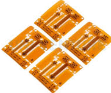
High speed pcb routing
Techniques For Optimizing High Speed PCB Routing
High-speed PCB routing is a critical aspect of modern electronic design, where the demand for faster and more efficient devices continues to grow. As electronic components become increasingly sophisticated, the need for effective techniques to optimize high-speed PCB routing becomes paramount.
One of the primary considerations in high-speed PCB routing is signal integrity,
which can be significantly affected by factors such as impedance mismatches, crosstalk, and electromagnetic interference. To address these challenges, designers must employ a variety of techniques to ensure that signals are transmitted accurately and efficiently across the PCB.
Firstly, impedance control is essential in high-speed PCB routing.
Impedance mismatches can lead to signal reflections, which degrade signal quality and can cause data errors. To mitigate this, designers must carefully calculate and control the impedance of traces by considering factors such as trace width, thickness, and the dielectric properties of the substrate material. Utilizing controlled impedance traces ensures that the signal integrity is maintained, thereby enhancing the overall performance of the PCB.
In addition to impedance control, minimizing crosstalk is another crucial aspect of optimizing high-speed PCB routing.
Crosstalk occurs when signals in adjacent traces interfere with each other, leading to potential data corruption. To reduce crosstalk, designers can increase the spacing between traces, use differential pairs, and implement ground planes. Differential pairs, in particular, are effective as they allow for the cancellation of noise and improve signal integrity. Ground planes, on the other hand, provide a return path for signals and help in reducing electromagnetic interference.
Moreover, the use of vias in high-speed PCB routing requires careful consideration.
While vias are necessary for connecting different layers of a PCB, they can introduce parasitic inductance and capacitance, which can adversely affect signal integrity. To optimize the use of vias, designers should minimize their number and ensure that they are placed strategically. Additionally, using blind or buried vias can help in reducing the impact on signal integrity by limiting the number of layers a via traverses.
Another technique for optimizing high-speed PCB routing is the implementation of proper layer stack-up.
A well-designed layer stack-up can significantly enhance signal integrity by providing controlled impedance and reducing electromagnetic interference. Typically, a multi-layer PCB with dedicated power and ground planes is preferred, as it allows for better signal isolation and reduces the potential for crosstalk. Furthermore, placing high-speed signal layers adjacent to ground planes can help in maintaining signal integrity.
Signal routing strategies also play a vital role in optimizing high-speed PCB routing.
Designers should aim to keep trace lengths as short as possible to reduce signal delay and attenuation. Additionally, avoiding sharp angles and using curved or 45-degree bends can help in minimizing signal reflections. It is also advisable to route high-speed signals on inner layers, where they are shielded by ground planes, to further enhance signal integrity.
In conclusion, optimizing high-speed PCB routing requires a comprehensive approach that considers various factors affecting signal integrity.
By employing techniques such as impedance control, minimizing crosstalk, strategic via placement, proper layer stack-up, and effective signal routing strategies, designers can ensure that their PCBs meet the demands of modern high-speed applications. As technology continues to advance, the importance of these techniques will only grow, making them indispensable tools in the arsenal of PCB designers.

Common Challenges In High Speed PCB Design
High-speed PCB design is a critical aspect of modern electronics, where the demand for faster and more efficient devices continues to grow. As technology advances, the challenges associated with high-speed PCB routing become increasingly complex.
One of the primary challenges in high-speed PCB design is signal integrity.
As the frequency of signals increases, the potential for signal degradation due to factors such as crosstalk, reflection, and electromagnetic interference (EMI) also rises. These issues can lead to data corruption and system failures, making it essential for designers to carefully consider the layout and routing of traces to minimize these effects.
Moreover, impedance control is another significant challenge in high-speed PCB design.
Maintaining consistent impedance is crucial for ensuring signal integrity, as variations can cause reflections and signal loss. Designers must meticulously calculate and control the width, spacing, and layer stack-up of traces to achieve the desired impedance levels. This often requires advanced simulation tools and precise manufacturing processes to ensure that the final product meets the necessary specifications.
In addition to signal integrity and impedance control, managing power distribution is a critical concern in high-speed PCB design.
As devices become more complex, the power requirements increase, necessitating efficient power distribution networks (PDNs). A poorly designed PDN can lead to voltage drops, increased noise, and thermal issues, all of which can adversely affect the performance of the device. To address this, designers must carefully plan the placement of power and ground planes, as well as the routing of power traces, to ensure adequate power delivery and minimize noise.
Thermal management is another challenge that cannot be overlooked in high-speed PCB design.
As components operate at higher speeds, they generate more heat, which can lead to thermal stress and potential failure if not properly managed. Effective thermal management involves the strategic placement of components, the use of thermal vias and heat sinks, and the selection of materials with appropriate thermal conductivity. By addressing these factors, designers can ensure that the PCB operates within safe temperature limits, thereby enhancing reliability and longevity.
Furthermore, the miniaturization of electronic devices adds another layer of complexity to high-speed PCB design.
As devices become smaller, the available space for routing traces and placing components is reduced, making it more challenging to maintain signal integrity and manage power distribution. Designers must employ innovative techniques, such as using multiple layers and advanced routing strategies, to overcome these spatial constraints while still meeting performance requirements.
Finally, the rapid pace of technological advancement means that high-speed PCB designers must continuously update their knowledge and skills to keep up with new materials, tools, and methodologies.
This requires ongoing education and adaptation to emerging trends and standards in the industry. By staying informed and embracing new technologies, designers can effectively address the challenges of high-speed PCB routing and contribute to the development of cutting-edge electronic devices.
In conclusion, high-speed PCB design presents a myriad of challenges that require careful consideration and expertise. From signal integrity and impedance control to power distribution and thermal management, each aspect plays a crucial role in the overall performance and reliability of the device. By understanding and addressing these challenges, designers can create high-speed PCBs that meet the demands of modern technology and pave the way for future innovations.
Importance Of Signal Integrity In High Speed PCB Routing
In the realm of high-speed printed circuit board (PCB) design, signal integrity emerges as a critical factor that can significantly influence the performance and reliability of electronic systems. As technology advances, the demand for faster data transmission rates and higher processing speeds continues to grow, necessitating meticulous attention to signal integrity during the PCB routing process. Signal integrity refers to the preservation of the quality and fidelity of electrical signals as they traverse the complex pathways of a PCB. Ensuring signal integrity is paramount, as any degradation can lead to data errors, system malfunctions, or even complete failure of the electronic device.
One of the primary challenges in high-speed PCB routing is the management of signal reflections, which can occur when there is a mismatch in impedance along the transmission line.
These reflections can cause signal distortion, leading to data corruption. To mitigate this issue, designers must carefully control the impedance of the traces by considering factors such as trace width, spacing, and the dielectric properties of the substrate material. By maintaining consistent impedance, reflections can be minimized, thereby preserving signal integrity.
Moreover, crosstalk is another phenomenon that poses a threat to signal integrity in high-speed PCB designs.
Crosstalk occurs when a signal in one trace induces an unwanted signal in an adjacent trace, potentially leading to interference and data errors. To address this, designers often employ techniques such as increasing the spacing between traces, using differential signaling, and implementing ground planes to provide effective isolation. These strategies help to reduce the coupling between traces, thereby minimizing crosstalk and enhancing signal integrity.
In addition to reflections and crosstalk, electromagnetic interference (EMI) is a significant concern in high-speed PCB routing.
EMI can originate from both internal and external sources, disrupting the normal operation of electronic circuits. To combat EMI, designers can utilize shielding techniques, such as placing ground planes strategically and using vias to connect different layers of the PCB. Furthermore, careful routing of high-speed signals away from potential sources of interference can also contribute to maintaining signal integrity.
Transitioning to another crucial aspect, the role of power integrity cannot be overlooked when discussing signal integrity in high-speed PCB routing.
Power integrity involves ensuring that the power delivery network (PDN) provides a stable and noise-free supply voltage to all components on the PCB. Any fluctuations or noise in the power supply can adversely affect signal integrity, leading to timing errors and degraded performance. To achieve robust power integrity, designers must focus on optimizing the PDN by minimizing inductance and resistance, using decoupling capacitors effectively, and ensuring proper grounding.
Furthermore, as data rates increase, the effects of signal attenuation become more pronounced.
Signal attenuation refers to the loss of signal strength as it propagates through the PCB traces. This can be exacerbated by factors such as trace length, frequency, and the dielectric properties of the substrate. To counteract signal attenuation, designers may employ techniques such as using low-loss materials, optimizing trace geometry, and incorporating signal conditioning components like equalizers and amplifiers.
In conclusion, the importance of signal integrity in high-speed PCB routing cannot be overstated. As electronic devices continue to evolve, maintaining signal integrity becomes increasingly challenging yet essential. By addressing issues such as reflections, crosstalk, EMI, power integrity, and signal attenuation, designers can ensure that high-speed PCBs perform reliably and efficiently. Through careful planning and implementation of best practices, the integrity of signals can be preserved, paving the way for the successful operation of advanced electronic systems.

Advanced Tools For High Speed PCB Layout Design
In the realm of high-speed printed circuit board (PCB) design, the demand for advanced tools has become increasingly critical. As electronic devices continue to evolve, the need for faster data transmission and higher performance has driven the development of sophisticated PCB layout design tools. These tools are essential for engineers to manage the complexities associated with high-speed signals, ensuring signal integrity and minimizing electromagnetic interference (EMI).
One of the primary challenges in high-speed PCB design is maintaining signal integrity.
As signal frequencies increase, the potential for signal degradation due to factors such as crosstalk, reflection, and impedance mismatches also rises. Advanced PCB layout tools offer features that help designers address these issues effectively. For instance, they provide impedance control capabilities, allowing designers to specify and maintain the desired impedance throughout the signal path. This is crucial for minimizing reflections and ensuring that signals are transmitted cleanly and efficiently.
Moreover, these tools often include simulation features that enable designers to model and analyze the behavior of high-speed signals before the physical board is manufactured.
By simulating the signal paths, designers can identify potential issues such as timing errors or signal distortion and make necessary adjustments to the layout. This proactive approach not only saves time and resources but also enhances the reliability of the final product.
Transitioning to another critical aspect, the management of electromagnetic interference is another area where advanced PCB layout tools prove invaluable.
High-speed signals can generate significant EMI, which can interfere with the operation of other components on the board or even affect nearby electronic devices. To mitigate this, modern PCB design tools offer features such as automated routing and placement optimization. These features help in strategically placing components and routing traces to minimize EMI, ensuring compliance with regulatory standards and improving overall device performance.
Furthermore, as the complexity of PCB designs increases, the need for efficient design collaboration becomes apparent.
Advanced PCB layout tools often come equipped with collaborative features that allow multiple designers to work on a project simultaneously. This collaborative approach not only speeds up the design process but also reduces the likelihood of errors, as team members can easily share insights and feedback in real-time.
In addition to collaboration, the integration of design rule checks (DRC) within these tools is another significant advantage.
DRCs automatically verify that the design adheres to predefined rules and constraints, such as trace width, spacing, and layer stack-up. This automated verification process helps in identifying potential design violations early, reducing the risk of costly rework and ensuring that the final product meets the desired specifications.
Finally, the advent of machine learning and artificial intelligence in PCB design tools is paving the way for even more advanced capabilities.
These technologies can analyze vast amounts of design data to provide insights and recommendations, further enhancing the efficiency and effectiveness of the design process. By leveraging AI, designers can optimize routing paths, predict potential issues, and even automate certain aspects of the design, leading to faster development cycles and improved product performance.
In conclusion, the use of advanced tools in high-speed PCB layout design is indispensable for addressing the challenges posed by modern electronic devices. By providing features that enhance signal integrity, manage EMI, facilitate collaboration, and integrate intelligent technologies, these tools empower designers to create reliable, high-performance PCBs that meet the demands of today’s fast-paced technological landscape.