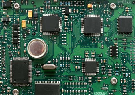
High frequency pcb design tips
Optimizing Signal Integrity in High Frequency PCB Design
In the realm of high frequency printed circuit board (PCB) design, optimizing signal integrity is paramount to ensuring the reliable performance of electronic devices. As frequencies increase, the challenges associated with maintaining signal integrity become more pronounced, necessitating a meticulous approach to design.
One of the primary considerations in high frequency PCB design is the selection of appropriate materials.
The dielectric constant and loss tangent of the substrate material significantly influence signal propagation. Low-loss materials, such as Rogers or Teflon-based laminates, are often preferred for high frequency applications due to their ability to minimize signal attenuation and distortion.
Transitioning from material selection, the layout of the PCB plays a crucial role in signal integrity.
The placement of components and routing of traces must be carefully planned to reduce electromagnetic interference (EMI) and crosstalk. It is advisable to keep high frequency traces as short as possible and to use microstrip or stripline configurations to control impedance. Impedance matching is essential to prevent signal reflections, which can degrade signal quality. Utilizing controlled impedance traces ensures that the characteristic impedance of the trace matches that of the source and load, thereby minimizing reflections.
Moreover, the use of ground planes is instrumental in enhancing signal integrity.
A continuous ground plane provides a return path for signals, reducing the loop area and minimizing inductive coupling. This, in turn, helps to mitigate EMI and improve signal quality. Additionally, ground planes can be used to create controlled impedance environments, further aiding in impedance matching. It is also beneficial to employ via stitching around high frequency traces to maintain a consistent ground reference and reduce the potential for signal integrity issues.
In addition to layout considerations, the choice of components and their placement can significantly impact signal integrity.
High frequency components, such as capacitors and inductors, should be selected based on their frequency response characteristics. Surface mount components are generally preferred over through-hole components due to their lower parasitic inductance and capacitance. Furthermore, placing decoupling capacitors close to power pins can help to stabilize power delivery and reduce noise.
Signal integrity can also be optimized through careful attention to power distribution networks (PDNs).
A well-designed PDN ensures that power is delivered efficiently to all components, minimizing voltage fluctuations and noise. This can be achieved by using wide power traces and multiple vias to reduce inductance and resistance. Additionally, incorporating power and ground planes in a multilayer PCB design can further enhance the performance of the PDN.
Finally, simulation and testing are indispensable in the process of optimizing signal integrity in high frequency PCB design.
Electromagnetic simulation tools can be used to model and analyze the behavior of high frequency signals, allowing designers to identify potential issues and make necessary adjustments before fabrication. Post-fabrication testing, such as time-domain reflectometry (TDR) and vector network analysis, can provide valuable insights into the actual performance of the PCB, enabling further refinements.
In conclusion, optimizing signal integrity in high frequency PCB design requires a comprehensive approach that encompasses material selection, layout, component choice, and power distribution. By addressing these factors and employing simulation and testing, designers can ensure that their high frequency PCBs deliver the desired performance and reliability.
Effective Layer Stackup Strategies for High Frequency PCBs
In the realm of high frequency printed circuit board (PCB) design, the layer stackup plays a pivotal role in determining the overall performance and reliability of the circuit. As frequencies increase, the electromagnetic behavior of the PCB becomes more pronounced, necessitating meticulous attention to the stackup configuration.
An effective layer stackup strategy not only mitigates signal integrity issues but also enhances the electromagnetic compatibility (EMC) of the design. To achieve optimal results, designers must consider several key factors, including material selection, layer arrangement, and impedance control.
Firstly, material selection is crucial in high frequency PCB design.
The dielectric material used between the layers significantly impacts signal propagation. Materials with low dielectric constant (Dk) and low dissipation factor (Df) are preferred as they reduce signal loss and ensure faster signal transmission.
Common materials such as FR-4 may not suffice for high frequency applications, prompting the use of specialized substrates like Rogers or Taconic, which offer superior electrical properties. By carefully selecting the appropriate material, designers can minimize signal attenuation and maintain signal integrity across the board.
Transitioning to layer arrangement, it is essential to strategically position the signal and ground layers to optimize performance.
A common practice is to place high-speed signal layers adjacent to continuous ground planes. This configuration provides a low-inductance return path for the signals, thereby reducing electromagnetic interference (EMI) and crosstalk. Additionally, maintaining symmetry in the stackup can help balance the mechanical stresses during manufacturing and operation, further enhancing the board’s reliability. By thoughtfully arranging the layers, designers can effectively manage electromagnetic fields and improve the overall functionality of the PCB.
Moreover, impedance control is a critical aspect of high frequency PCB design.
Impedance mismatches can lead to signal reflections, which degrade signal quality and increase the likelihood of data errors. To address this, designers must calculate and control the characteristic impedance of the transmission lines.
This involves adjusting the trace width, spacing, and dielectric thickness to achieve the desired impedance value. Utilizing simulation tools can aid in predicting and fine-tuning these parameters, ensuring that the PCB meets the stringent requirements of high frequency applications. By maintaining consistent impedance throughout the board, designers can enhance signal integrity and reduce the risk of performance issues.
In addition to these considerations, thermal management should not be overlooked in high frequency PCB design.
As frequencies rise, so does the potential for heat generation, which can adversely affect the board’s performance and longevity. Implementing thermal vias, heat sinks, and appropriate copper thickness can help dissipate heat effectively, ensuring that the PCB operates within safe temperature limits. By integrating thermal management strategies into the layer stackup design, designers can prevent overheating and maintain the reliability of the circuit.
In conclusion, effective layer stackup strategies are indispensable for high frequency PCB design.
By carefully selecting materials, arranging layers strategically, controlling impedance, and managing thermal aspects, designers can create PCBs that perform reliably in demanding high frequency environments. As technology continues to advance, the importance of these strategies will only grow, underscoring the need for designers to stay informed and adept in their application. Through meticulous planning and execution, high frequency PCBs can achieve the desired performance, paving the way for innovation and progress in various technological fields.
Managing Thermal Performance in High Frequency PCB Layouts
In the realm of high frequency PCB design, managing thermal performance is a critical aspect that demands meticulous attention. As electronic devices continue to shrink in size while increasing in functionality, the challenge of dissipating heat effectively becomes more pronounced. High frequency circuits, in particular, are susceptible to thermal issues due to their rapid switching speeds and dense component placement. Therefore, understanding and implementing strategies to manage thermal performance is essential for ensuring the reliability and longevity of these circuits.
To begin with, one of the fundamental considerations in managing thermal performance is the selection of appropriate materials.
The choice of substrate material can significantly influence the thermal conductivity of the PCB. Materials with higher thermal conductivity, such as aluminum or copper-based substrates, can facilitate better heat dissipation compared to traditional FR-4 materials. Additionally, the use of thermal vias can enhance heat transfer from the surface of the PCB to the inner layers or heat sinks, thereby reducing the thermal resistance.
Moreover, the layout of components plays a pivotal role in thermal management.
Placing heat-generating components, such as power amplifiers or voltage regulators, in areas with adequate airflow can help dissipate heat more effectively. It is also advisable to distribute these components evenly across the PCB to prevent localized hotspots. Furthermore, incorporating thermal reliefs in the design can aid in minimizing the thermal stress on solder joints, which is crucial for maintaining the mechanical integrity of the connections.
In addition to material selection and component placement, the use of thermal management tools and simulations can provide valuable insights into the thermal behavior of the PCB.
Thermal simulation software allows designers to model the heat distribution across the PCB and identify potential problem areas before physical prototyping. By simulating various scenarios, designers can optimize the layout and make informed decisions about the placement of heat sinks, fans, or other cooling mechanisms.
Transitioning to the topic of cooling solutions, it is important to consider both passive and active cooling methods.
Passive cooling, which relies on natural convection and radiation, can be effective for low to moderate power applications. This can be achieved through the use of heat sinks, thermal pads, or spreaders that increase the surface area for heat dissipation.
On the other hand, active cooling methods, such as fans or liquid cooling systems, may be necessary for high-power applications where passive methods are insufficient. These solutions can significantly enhance the thermal performance but may introduce additional complexity and cost to the design.
Furthermore, it is essential to consider the impact of thermal expansion on high frequency PCBs.
Variations in temperature can lead to expansion and contraction of materials, potentially causing mechanical stress and affecting the electrical performance of the circuit. To mitigate these effects, designers should account for the coefficient of thermal expansion (CTE) of the materials used and ensure compatibility between different layers and components.
In conclusion, managing thermal performance in high frequency PCB layouts is a multifaceted challenge that requires a comprehensive approach. By carefully selecting materials, optimizing component placement, utilizing thermal simulations, and implementing appropriate cooling solutions, designers can effectively address thermal issues and enhance the reliability of high frequency circuits. As technology continues to evolve, staying abreast of advancements in thermal management techniques will be crucial for meeting the demands of increasingly complex electronic systems.

Best Practices for Via Design in High Frequency PCBs
In the realm of high frequency printed circuit board (PCB) design, the meticulous consideration of via design is paramount to ensuring optimal performance and signal integrity.
Vias, which are the conductive pathways that connect different layers of a PCB, play a crucial role in the overall functionality of high frequency circuits.
As frequencies increase, the impact of vias on signal integrity becomes more pronounced, necessitating a strategic approach to their design. To begin with, understanding the electrical characteristics of vias is essential. Vias introduce inductance and capacitance into the circuit, which can affect signal propagation, especially at high frequencies.
Therefore, minimizing via inductance is a primary objective.
This can be achieved by reducing the via length and increasing the via diameter, as shorter and wider vias exhibit lower inductance. Additionally, using multiple vias in parallel for power and ground connections can further reduce inductance, thereby enhancing signal integrity.
Transitioning to the aspect of via placement, it is crucial to position vias strategically to minimize their impact on signal paths.
Placing vias directly in the signal path can introduce unwanted reflections and impedance discontinuities. To mitigate this, vias should be placed off the main signal path whenever possible. Moreover, maintaining a consistent via-to-trace width ratio is vital to avoid impedance mismatches.
This consistency helps in preserving the characteristic impedance of the transmission line, which is critical for high frequency applications.
Furthermore, the use of via stitching is a recommended practice in high frequency PCB design. Via stitching involves placing multiple vias around a signal trace or a ground plane to create a low-inductance path for return currents. This technique is particularly beneficial in reducing electromagnetic interference (EMI) and improving signal integrity by providing a more direct return path for high frequency signals.
In addition to via placement and stitching, the choice of via type is another important consideration.
Blind and buried vias, which do not pass through the entire PCB, can be advantageous in high frequency designs. These vias help in reducing the parasitic effects associated with through-hole vias, as they limit the via length and, consequently, the inductance. However, it is important to note that the use of blind and buried vias can increase manufacturing complexity and cost. Therefore, a careful evaluation of the trade-offs is necessary when deciding on the via type. Another best practice in via design is the implementation of back-drilling. Back-drilling involves removing the unused portion of a via stub, which can act as an antenna and cause signal reflections. By eliminating these stubs, back-drilling helps in reducing signal distortion and improving the overall performance of high frequency PCBs.
Finally, it is essential to consider the thermal and mechanical aspects of via design.
High frequency PCBs often generate significant heat, and vias can serve as thermal conduits to dissipate this heat. Ensuring adequate thermal vias in heat-sensitive areas can prevent overheating and enhance the reliability of the PCB. Additionally, vias should be designed to withstand mechanical stresses during manufacturing and operation to prevent failures. In conclusion, the design of vias in high frequency PCBs requires a comprehensive approach that considers electrical, thermal, and mechanical factors. By adhering to best practices such as minimizing via inductance, strategic via placement, and the use of advanced techniques like via stitching and back-drilling, designers can significantly enhance the performance and reliability of high frequency circuits.