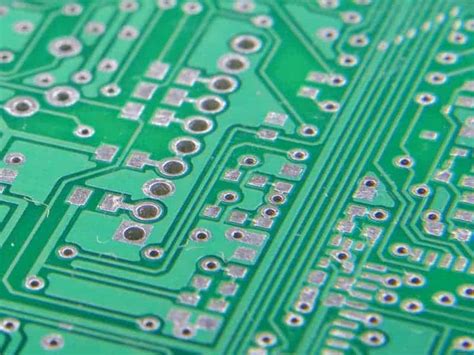
Components on flex pcb
Advantages Of Using Flex PCB Components In Modern Electronics
In the rapidly evolving landscape of modern electronics, the demand for more compact, efficient, and reliable devices has led to significant advancements in circuit board technology. Among these innovations, flexible printed circuit boards (flex PCBs) have emerged as a pivotal component, offering numerous advantages over traditional rigid PCBs. The integration of flex PCB components into electronic devices has revolutionized design possibilities, enabling manufacturers to meet the growing consumer demand for smaller, lighter, and more versatile products.
One of the primary advantages of using flex PCB components is their inherent flexibility, which allows for the creation of complex, three-dimensional configurations.
This adaptability is particularly beneficial in applications where space is at a premium, such as in wearable technology, medical devices, and compact consumer electronics. By conforming to the contours of the device, flex PCBs enable designers to maximize the use of available space, thereby reducing the overall size and weight of the product. This capability not only enhances the aesthetic appeal of the device but also improves its portability and user-friendliness.
Moreover, the use of flex PCB components contributes to increased reliability and durability in electronic devices.
The flexible nature of these boards allows them to absorb and withstand mechanical stresses, such as vibrations and bending, that would otherwise compromise the integrity of a rigid PCB. This resilience is particularly advantageous in applications subject to frequent movement or harsh environmental conditions, such as automotive and aerospace industries. By reducing the risk of mechanical failure, flex PCBs enhance the longevity and performance of electronic devices, ultimately leading to greater consumer satisfaction and reduced maintenance costs.
In addition to their mechanical benefits, flex PCB components offer significant electrical advantages.
The ability to design circuits with shorter interconnections reduces the potential for signal loss and electromagnetic interference, thereby improving the overall performance of the device. This feature is especially critical in high-frequency applications, where maintaining signal integrity is paramount. Furthermore, the use of flex PCBs can lead to a reduction in the number of connectors and solder joints required, which not only simplifies the assembly process but also minimizes potential points of failure.
Another noteworthy advantage of flex PCB components is their contribution to cost efficiency in the manufacturing process.
Although the initial design and production of flex PCBs may be more complex and costly than their rigid counterparts, the long-term benefits often outweigh these initial expenses. The reduction in material usage, assembly time, and the need for additional components can lead to significant cost savings in mass production. Additionally, the enhanced reliability and durability of flex PCBs can result in lower warranty and repair costs, further contributing to their economic appeal.
As the demand for more sophisticated and compact electronic devices continues to grow, the role of flex PCB components in modern electronics is likely to expand.
Their unique combination of flexibility, reliability, and electrical performance makes them an ideal choice for a wide range of applications, from consumer electronics to industrial and medical devices. By embracing the advantages of flex PCBs, manufacturers can not only meet the evolving needs of the market but also drive innovation and efficiency in electronic design and production. In conclusion, the integration of flex PCB components represents a significant advancement in the field of electronics, offering a multitude of benefits that are poised to shape the future of technology.
Key Considerations For Designing Components On Flex PCBs
When designing components on flexible printed circuit boards (flex PCBs), several key considerations must be taken into account to ensure optimal performance and reliability. Flex PCBs offer unique advantages, such as the ability to bend and conform to various shapes, making them ideal for compact and complex electronic devices. However, their design requires careful attention to detail to address the challenges posed by their flexibility and the materials used.
One of the primary considerations in designing components on flex PCBs is the selection of appropriate materials.
The substrate material must be flexible yet durable enough to withstand repeated bending and flexing. Polyimide is commonly used due to its excellent thermal stability and mechanical properties. Additionally, the choice of adhesive and coverlay materials is crucial, as they must provide adequate protection to the circuitry while maintaining flexibility. These materials must also be compatible with the thermal and chemical processes involved in manufacturing.
Another important aspect is the layout of the circuit traces.
Designers must consider the bend radius and the potential for mechanical stress on the traces. To minimize stress, traces should be routed perpendicular to the bend axis whenever possible. Furthermore, the use of curved traces instead of sharp angles can help distribute stress more evenly, reducing the risk of trace cracking or delamination. It is also advisable to maintain a consistent trace width and spacing to ensure uniform electrical performance and to avoid impedance mismatches.
The placement of components on flex PCBs requires careful planning.
Components should be positioned in areas that experience minimal bending to reduce mechanical stress. When placing components in bend areas is unavoidable, using flexible components or designing the board with stiffeners can help mitigate potential issues. Additionally, the weight and size of components should be considered, as heavier components may require additional support to prevent damage during flexing.
Thermal management is another critical consideration in flex PCB design.
The flexible nature of these boards can make heat dissipation more challenging compared to rigid PCBs. Designers must ensure that heat-generating components are adequately spaced and that thermal vias or heat sinks are used to dissipate heat effectively. This is particularly important in high-power applications where excessive heat can lead to component failure or reduced performance.
Signal integrity is also a key factor in the design of flex PCBs.
The flexible nature of the board can introduce signal integrity issues, such as crosstalk and electromagnetic interference (EMI). To address these challenges, designers should use controlled impedance traces and incorporate shielding techniques where necessary. Additionally, maintaining a consistent ground plane can help reduce EMI and improve overall signal performance.
Finally, manufacturability and cost considerations should not be overlooked.
The complexity of flex PCB designs can impact manufacturing processes and costs. Designers should work closely with manufacturers to ensure that the design is feasible and cost-effective. This includes considering factors such as panel utilization, layer count, and the use of advanced manufacturing techniques like laser drilling or sequential lamination.
In conclusion, designing components on flex PCBs requires a comprehensive understanding of the unique challenges and considerations associated with these versatile boards. By carefully selecting materials, optimizing trace layouts, strategically placing components, managing thermal and signal integrity, and considering manufacturability, designers can create reliable and efficient flex PCB designs that meet the demands of modern electronic applications.
Common Challenges In Manufacturing Flex PCB Components
In the realm of modern electronics, flexible printed circuit boards (flex PCBs) have emerged as a pivotal innovation, offering a versatile solution for a wide range of applications. However, the manufacturing of flex PCB components presents a unique set of challenges that must be meticulously addressed to ensure optimal performance and reliability. Understanding these challenges is crucial for manufacturers aiming to harness the full potential of flex PCBs.
One of the primary challenges in manufacturing flex PCB components is the selection of appropriate materials.
Unlike rigid PCBs, flex PCBs require materials that can withstand bending and flexing without compromising electrical performance. Polyimide is commonly used due to its excellent thermal stability and flexibility. However, the choice of adhesive and copper foil also plays a critical role in the overall durability and functionality of the flex PCB. Manufacturers must carefully balance these materials to achieve the desired flexibility while maintaining structural integrity.
In addition to material selection, the design process poses significant challenges.
Flex PCBs often need to fit into compact and irregularly shaped spaces, necessitating intricate design considerations. The layout must account for potential stress points that could lead to mechanical failure over time. Moreover, the routing of traces requires precision to avoid issues such as signal interference and impedance mismatches. Advanced design software and simulation tools are indispensable in this phase, allowing engineers to visualize and optimize the flex PCB layout before production.
Transitioning from design to production, the manufacturing process itself introduces further complexities.
The delicate nature of flex PCBs demands precise handling and processing techniques. For instance, the etching process must be carefully controlled to prevent over-etching, which can weaken the copper traces. Similarly, the lamination process requires uniform pressure and temperature to ensure proper adhesion of the layers. Any deviation can result in delamination, compromising the board’s functionality.
Moreover, the assembly of components onto flex PCBs presents its own set of challenges.
The flexible nature of the substrate can lead to difficulties in maintaining alignment during component placement. This is particularly critical for surface-mount technology (SMT) components, where precise positioning is essential for reliable soldering. Automated assembly equipment must be calibrated to accommodate the unique characteristics of flex PCBs, ensuring that components are accurately placed and soldered without damaging the substrate.
Testing and quality assurance are also crucial stages in the manufacturing of flex PCB components.
Due to their flexible nature, these boards are more susceptible to mechanical stress during testing. Manufacturers must employ specialized testing methods to evaluate the electrical performance and mechanical resilience of flex PCBs. This often involves a combination of visual inspections, electrical testing, and mechanical stress tests to identify any potential defects or weaknesses.
In conclusion, while flex PCBs offer significant advantages in terms of design flexibility and application versatility, their manufacturing process is fraught with challenges that require careful consideration and expertise.
From material selection and design intricacies to precise manufacturing techniques and rigorous testing, each stage demands meticulous attention to detail. By addressing these challenges, manufacturers can ensure the production of high-quality flex PCB components that meet the demanding requirements of modern electronic applications. As technology continues to evolve, overcoming these challenges will be essential for the continued advancement and adoption of flex PCBs in various industries.
Innovations In Flex PCB Component Technology
In recent years, the field of flexible printed circuit boards (FPCBs) has witnessed significant advancements, driven by the increasing demand for compact, lightweight, and versatile electronic devices. These innovations in flex PCB component technology have not only enhanced the performance and reliability of electronic products but have also expanded their application across various industries. As we delve into the components of flex PCBs, it is essential to understand the unique characteristics that distinguish them from traditional rigid PCBs.
To begin with, the substrate material used in flex PCBs is a critical component that sets them apart.
Unlike rigid PCBs, which typically use fiberglass-reinforced epoxy, flex PCBs employ flexible materials such as polyimide or polyester films. These materials provide the necessary flexibility and durability, allowing the circuit to bend and conform to different shapes without compromising its functionality. This flexibility is particularly advantageous in applications where space constraints and dynamic movements are prevalent, such as in wearable technology and medical devices.
Moreover, the conductive layers in flex PCBs are another vital component that contributes to their functionality.
These layers are usually made of copper, which is deposited onto the flexible substrate through various methods, including electroplating and etching. The choice of copper thickness and the method of deposition play a crucial role in determining the electrical performance and mechanical resilience of the flex PCB. As technology advances, manufacturers are exploring new techniques to enhance the conductivity and reliability of these layers, ensuring that they can withstand repeated flexing and environmental stresses.
In addition to the substrate and conductive layers, the adhesive system used in flex PCBs is a key component that ensures the integrity of the circuit.
The adhesive bonds the various layers together, providing mechanical support and electrical insulation. Innovations in adhesive technology have led to the development of high-performance adhesives that offer improved thermal stability, chemical resistance, and flexibility. These advancements are particularly important in applications where the flex PCB is exposed to harsh conditions, such as in automotive and aerospace industries.
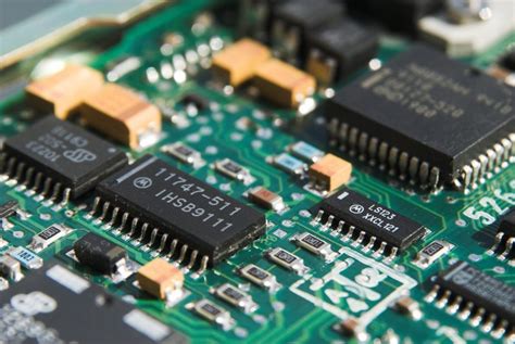
Furthermore, the integration of components onto flex PCBs has seen remarkable progress, with surface mount technology (SMT) playing a pivotal role.
SMT allows for the placement of smaller and more complex components directly onto the surface of the flex PCB, optimizing space and enhancing performance. This method is complemented by the use of advanced assembly techniques, such as automated pick-and-place machines and reflow soldering, which ensure precision and efficiency in component placement. As a result, flex PCBs can accommodate a higher density of components, enabling more sophisticated functionalities in compact devices.
As we look to the future, the ongoing research and development in flex PCB component technology promise even greater innovations.
The exploration of new materials, such as conductive inks and nanomaterials, holds the potential to revolutionize the design and capabilities of flex PCBs. Additionally, the integration of flexible components, such as sensors and batteries, directly onto the flex PCB is an area of active investigation, offering the possibility of creating fully flexible electronic systems.
In conclusion, the advancements in flex PCB component technology have significantly contributed to the evolution of electronic devices, offering unparalleled flexibility, reliability, and performance. As industries continue to push the boundaries of what is possible, the role of flex PCBs will undoubtedly expand, paving the way for new applications and innovations in the ever-evolving landscape of electronics.
Best Practices For Assembling Components On Flex PCBs
As the demand for compact and versatile electronic devices continues to rise, flexible printed circuit boards (flex PCBs) have become increasingly popular due to their ability to bend and conform to various shapes. This adaptability makes them ideal for applications in industries such as consumer electronics, automotive, and medical devices. However, assembling components on flex PCBs requires careful consideration and adherence to best practices to ensure reliability and performance. Understanding these practices is crucial for engineers and manufacturers aiming to optimize the functionality and longevity of their products.
To begin with, selecting the appropriate materials is fundamental when working with flex PCBs.
The choice of substrate, typically polyimide, is critical due to its excellent thermal stability and flexibility. Additionally, the copper used for the conductive traces should be of high quality to withstand repeated bending without cracking. These material choices directly impact the board’s durability and performance, making it essential to prioritize quality over cost savings.
Once the materials are selected, the design phase plays a pivotal role in the successful assembly of components on flex PCBs.
It is important to incorporate design features that accommodate the board’s flexibility. For instance, traces should be routed in a manner that minimizes stress during bending. This can be achieved by using curved traces instead of sharp angles, which can act as stress concentrators. Furthermore, maintaining a uniform trace width and spacing helps distribute mechanical stress evenly across the board, reducing the risk of failure.
Transitioning to the assembly process, it is vital to employ techniques that account for the unique properties of flex PCBs.
Surface mount technology (SMT) is commonly used, but it requires adjustments to accommodate the board’s flexibility. For example, using a flexible solder paste can help absorb mechanical stress and prevent solder joint failure. Additionally, the reflow soldering process should be carefully controlled to avoid excessive heat, which can damage the polyimide substrate. Implementing a gradual temperature ramp-up and cool-down during reflow can mitigate thermal stress and enhance the reliability of solder joints.
Moreover, component placement on flex PCBs demands precision and attention to detail.
It is advisable to place components in areas with minimal bending to reduce mechanical stress on solder joints. When this is not possible, reinforcing the solder joints with additional support, such as underfill materials, can provide extra stability. Furthermore, using lightweight components can minimize the stress exerted on the board during flexing, thereby enhancing the overall durability of the assembly.
Testing and inspection are indispensable steps in ensuring the quality and reliability of assembled flex PCBs.
Conducting thorough electrical testing, such as continuity and insulation resistance tests, can identify potential issues before the product reaches the end user. Additionally, employing advanced inspection techniques, such as X-ray or automated optical inspection (AOI), can detect defects that may not be visible to the naked eye, such as voids in solder joints or misaligned components.
In conclusion, assembling components on flex PCBs requires a comprehensive understanding of the materials, design considerations, assembly techniques, and testing protocols. By adhering to best practices, manufacturers can harness the full potential of flex PCBs, delivering products that meet the demands of modern technology while ensuring reliability and performance. As the industry continues to evolve, staying informed about advancements in materials and assembly techniques will be key to maintaining a competitive edge in the market.