Demystifying vias in high speed pcb design
Understanding The Role Of Vias In High-Speed PCB Design
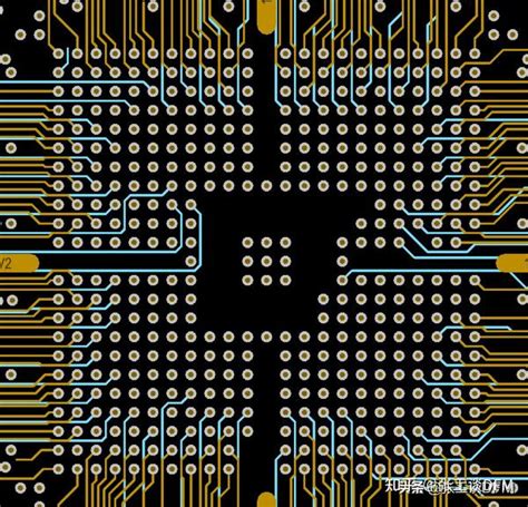
In the realm of high-speed printed circuit board (PCB) design, the role of vias is often a subject of considerable importance and complexity. Vias, which are essentially conductive pathways that allow electrical connections between different layers of a PCB, play a crucial role in ensuring the functionality and performance of high-speed circuits. As electronic devices continue to evolve, becoming more compact and faster, understanding the intricacies of vias becomes increasingly essential for engineers and designers.
To begin with, it is important to recognize that vias are not merely simple holes drilled into a PCB.
They are sophisticated components that can significantly influence the electrical characteristics of a circuit. In high-speed PCB design, vias are used to route signals between layers, connect power and ground planes, and facilitate thermal management. However, their presence can introduce unwanted parasitic inductance and capacitance, which can adversely affect signal integrity. Therefore, careful consideration must be given to their design and placement.
One of the primary challenges in high-speed PCB design is minimizing signal degradation.
Vias can contribute to signal reflection, crosstalk, and electromagnetic interference, all of which can degrade signal quality. To mitigate these issues, designers often employ techniques such as via stitching and back-drilling. Via stitching involves placing multiple vias around a signal via to provide a return path for high-frequency currents, thereby reducing loop inductance. Back-drilling, on the other hand, involves removing the unused portion of a via to minimize its stub effect, which can cause signal reflections.
Moreover, the choice of via type is another critical consideration.
There are several types of vias, including through-hole vias, blind vias, and buried vias, each with its own set of advantages and limitations. Through-hole vias extend through the entire PCB, making them robust and easy to manufacture, but they can occupy valuable space and introduce longer signal paths. Blind vias connect an outer layer to one or more inner layers without passing through the entire board, offering a space-saving solution. Buried vias, which are located entirely within the inner layers, provide even greater flexibility in routing but can increase manufacturing complexity and cost.
In addition to signal integrity, thermal management is another aspect where vias play a pivotal role.
High-speed circuits often generate significant heat, which must be efficiently dissipated to prevent performance degradation or damage. Thermal vias, which are vias specifically designed to conduct heat away from critical components, are commonly used to enhance thermal performance. By connecting heat-generating components to larger copper areas or heat sinks, thermal vias help maintain optimal operating temperatures.
Furthermore, the advent of advanced simulation tools has greatly facilitated the design and analysis of vias in high-speed PCBs.
These tools allow designers to model the electrical and thermal behavior of vias, enabling them to optimize via parameters such as size, shape, and placement. By leveraging these tools, designers can predict potential issues and make informed decisions to ensure the reliability and performance of their designs.
In conclusion, vias are indispensable elements in high-speed PCB design, serving as critical conduits for electrical signals and heat dissipation
. Their impact on signal integrity and thermal management cannot be overstated, necessitating careful consideration and strategic implementation. As technology continues to advance, the role of vias will undoubtedly remain a focal point in the pursuit of ever-faster and more efficient electronic devices. Understanding and mastering the complexities of vias is, therefore, an essential skill for any PCB designer aiming to excel in the high-speed domain.
Techniques For Minimizing Via-Induced Signal Integrity Issues
In the realm of high-speed printed circuit board (PCB) design, vias play a crucial role in facilitating electrical connections between different layers of a board. However, these seemingly simple structures can introduce significant signal integrity issues if not properly managed. Understanding the techniques for minimizing via-induced signal integrity problems is essential for engineers striving to optimize the performance of high-speed PCBs.
To begin with, it is important to recognize that vias can introduce parasitic inductance and capacitance, which can adversely affect signal integrity.
These parasitic elements can cause signal reflections, crosstalk, and impedance mismatches, all of which degrade the quality of high-speed signals. Therefore, one of the primary techniques for minimizing these issues is to carefully consider the via design itself. By optimizing the via geometry, such as its diameter and pad size, designers can reduce the parasitic effects. Smaller vias generally exhibit lower parasitic inductance and capacitance, which can help maintain signal integrity.
Moreover, the placement of vias is another critical factor.
Strategically positioning vias to minimize their impact on signal paths can significantly enhance performance. For instance, placing vias away from critical signal traces can reduce the likelihood of crosstalk and signal degradation. Additionally, using blind or buried vias, which do not pass through the entire board, can help in reducing the parasitic effects associated with through-hole vias. These types of vias are particularly beneficial in high-density designs where space is at a premium.
Transitioning to another effective technique, the use of via stitching can be instrumental in maintaining signal integrity.
Via stitching involves placing multiple vias around a signal trace to create a low-inductance return path for high-frequency signals. This technique is particularly useful in mitigating the effects of ground bounce and ensuring a stable reference plane for signals. By providing a continuous return path, via stitching helps in reducing electromagnetic interference (EMI) and maintaining signal quality.
Furthermore, the concept of back-drilling is gaining traction as a method to address via-induced signal integrity issues.
Back-drilling involves removing the unused portion of a via stub, which is the section of the via that extends beyond the signal layer. Via stubs can act as resonant structures, causing signal reflections and degradation. By eliminating these stubs, back-drilling effectively reduces the parasitic inductance and capacitance, thereby enhancing signal integrity.
In addition to these techniques, employing advanced simulation tools can provide valuable insights into the impact of vias on signal integrity.
These tools allow designers to model and analyze the electrical behavior of vias in a virtual environment, enabling them to identify potential issues and optimize via design before physical prototyping. By leveraging simulation, designers can make informed decisions about via placement, geometry, and other parameters, ultimately leading to improved signal integrity.
In conclusion, while vias are indispensable in high-speed PCB design, they can pose significant challenges to signal integrity if not properly managed.
By employing techniques such as optimizing via geometry, strategic placement, via stitching, back-drilling, and utilizing simulation tools, designers can effectively minimize via-induced signal integrity issues. These strategies not only enhance the performance of high-speed PCBs but also contribute to the overall reliability and efficiency of electronic systems. As technology continues to advance, mastering these techniques will remain a critical aspect of successful high-speed PCB design.
Best Practices For Via Placement In High-Speed Circuits
In the realm of high-speed printed circuit board (PCB) design, the strategic placement of vias is a critical factor that can significantly influence the performance and reliability of the circuit. Vias, which are essentially conductive pathways that allow signals to traverse between different layers of a PCB, play a pivotal role in maintaining signal integrity and minimizing electromagnetic interference. As high-speed circuits become increasingly complex, understanding the best practices for via placement is essential for engineers aiming to optimize their designs.
To begin with, it is important to recognize that the placement of vias can affect the impedance of a signal trace.
Impedance mismatches can lead to signal reflections, which degrade signal quality and can cause data errors. Therefore, one of the best practices is to ensure that vias are placed in a manner that minimizes impedance discontinuities. This can be achieved by maintaining a consistent via size and ensuring that the transition from the trace to the via is as smooth as possible. Additionally, using via stubs, which are the unused portions of a via, should be minimized or eliminated, as they can act as antennas and introduce unwanted resonances.
Moreover, the proximity of vias to other components and traces is another crucial consideration.
Placing vias too close to other signal paths can lead to crosstalk, where signals from one trace interfere with those on another. To mitigate this, it is advisable to maintain adequate spacing between vias and adjacent traces. This spacing helps to reduce electromagnetic coupling and ensures that signals remain isolated from one another. Furthermore, when routing differential pairs, it is beneficial to use vias symmetrically to preserve the balance of the pair, thereby maintaining the integrity of the differential signal.
Thermal management is another aspect where via placement plays a significant role.
High-speed circuits often generate substantial heat, and vias can be used to facilitate heat dissipation. By strategically placing thermal vias near heat-generating components, designers can create efficient thermal pathways that help in spreading heat across the PCB, thus preventing localized hotspots and ensuring the longevity of the components.
In addition to thermal considerations, the mechanical reliability of the PCB can be influenced by via placement.
Vias should be placed in a manner that avoids creating stress concentration points, which can lead to mechanical failures, especially in environments subject to vibration or thermal cycling. Distributing vias evenly across the board and avoiding clustering them in one area can enhance the mechanical robustness of the PCB.
Signal integrity can also be preserved by considering the return path of high-speed signals.
Vias can disrupt the return path, leading to increased loop inductance and potential signal integrity issues. To address this, it is advisable to place ground vias near signal vias, providing a continuous return path and minimizing loop area. This practice helps in reducing electromagnetic interference and maintaining signal quality.
In conclusion, the placement of vias in high-speed PCB design is a multifaceted challenge that requires careful consideration of electrical, thermal, and mechanical factors. By adhering to best practices such as minimizing impedance discontinuities, ensuring adequate spacing, facilitating thermal management, and preserving signal integrity, designers can enhance the performance and reliability of their high-speed circuits. As technology continues to advance, the importance of meticulous via placement will only grow, underscoring its critical role in the success of modern electronic designs.
Advanced Via Structures For Enhanced Performance In PCB Design
In the realm of high-speed printed circuit board (PCB) design, the role of vias is often underestimated, yet they are crucial for ensuring optimal performance. As electronic devices become increasingly complex, the demand for advanced via structures has grown, necessitating a deeper understanding of their impact on signal integrity and overall functionality. Vias, essentially the electrical connections between different layers of a PCB, can significantly influence the performance of high-speed circuits. Therefore, selecting the appropriate via structure is paramount for designers aiming to enhance the performance of their PCBs.
To begin with, it is essential to recognize the different types of vias available and their respective applications.
The most common types include through-hole vias, blind vias, and buried vias. Through-hole vias extend from the top to the bottom layer of the PCB, providing a straightforward connection but potentially introducing unwanted parasitic inductance and capacitance. In contrast, blind vias connect an outer layer to one or more inner layers without passing through the entire board, while buried vias connect only internal layers, offering a more compact solution. These advanced via structures are particularly beneficial in high-density interconnect (HDI) designs, where space is at a premium.
Transitioning to the impact of vias on signal integrity, it is crucial to consider the electrical characteristics they introduce.
Vias can act as inductors and capacitors, affecting the impedance of the signal path. This can lead to signal reflection, distortion, and loss, which are detrimental to high-speed applications. To mitigate these effects, designers often employ techniques such as via back-drilling, which removes the unused portion of a via to reduce its inductance and capacitance. Additionally, using smaller via diameters and optimizing the via pad and anti-pad sizes can further enhance signal integrity by minimizing parasitic effects.
Moreover, the choice of via structure can influence the thermal performance of a PCB.
Vias can serve as thermal conduits, facilitating heat dissipation from components to other layers or heat sinks. In high-speed designs, where power density is high, managing thermal performance is critical to prevent overheating and ensure reliability. Therefore, incorporating thermal vias strategically can help maintain optimal operating temperatures and enhance the longevity of the device.
Another consideration in advanced via structures is their impact on manufacturing complexity and cost.
While blind and buried vias offer significant performance benefits, they also increase the complexity of the manufacturing process. This can lead to higher production costs and longer lead times. Consequently, designers must balance the performance advantages of advanced via structures with the practical constraints of manufacturing and budgetary considerations.
In conclusion, demystifying vias in high-speed PCB design involves understanding their various types, electrical characteristics, and implications for signal integrity and thermal management. By carefully selecting and optimizing via structures, designers can significantly enhance the performance of their PCBs, ensuring that they meet the demands of modern high-speed applications. As technology continues to evolve, the role of advanced via structures will undoubtedly become even more critical, underscoring the importance of ongoing research and innovation in this field. Through a comprehensive approach to via design, engineers can unlock new levels of performance and reliability in their electronic devices.

