Flex pcb tolerances
Understanding Flex PCB Tolerances: Key Factors and Considerations
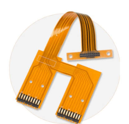
Flex PCB tolerances are a critical aspect of the design and manufacturing process for flexible printed circuit boards. These tolerances define the permissible limits of variation in the physical dimensions and electrical properties of the PCB, ensuring that the final product meets the required specifications and functions as intended. Understanding these tolerances is essential for engineers and designers to create reliable and efficient flex PCBs that can withstand the demands of their intended applications.
To begin with, it is important to recognize that flex PCBs differ significantly from their rigid counterparts.
The inherent flexibility of these circuits allows them to be bent, folded, and twisted, making them ideal for applications where space is limited or where the circuit needs to conform to a specific shape. However, this flexibility also introduces unique challenges in maintaining precise tolerances. The materials used in flex PCBs, such as polyimide films and adhesive layers, can exhibit variations in thickness and other properties, which can impact the overall performance of the circuit.
One of the key factors influencing flex PCB tolerances is the manufacturing process itself.
The etching, lamination, and drilling processes must be carefully controlled to ensure that the dimensions of the circuit traces, pads, and vias remain within specified limits. Any deviation from these tolerances can lead to issues such as signal integrity problems, increased resistance, or even complete circuit failure. Therefore, manufacturers must employ advanced techniques and equipment to maintain tight control over these processes.
Moreover, the design of the flex PCB plays a crucial role in determining the achievable tolerances
. Designers must consider factors such as the minimum trace width, spacing between traces, and the size and placement of vias. These design parameters must be carefully balanced to ensure that the circuit can be manufactured within the desired tolerances while also meeting the electrical and mechanical requirements of the application. Additionally, designers must account for the potential effects of environmental factors, such as temperature and humidity, which can cause the materials to expand or contract, further impacting the tolerances.
Another important consideration is the choice of materials used in the flex PCB.
Different materials have varying properties that can affect the achievable tolerances. For instance, the coefficient of thermal expansion (CTE) of the materials can influence how much the circuit will expand or contract with temperature changes. Selecting materials with compatible CTE values can help minimize these effects and maintain tighter tolerances. Furthermore, the adhesive systems used to bond the layers of the flex PCB can also impact the tolerances, as they may introduce additional variations in thickness and mechanical properties.
In conclusion, understanding flex PCB tolerances is essential for the successful design and manufacturing of flexible printed circuit boards.
By carefully considering factors such as the manufacturing process, design parameters, and material selection, engineers and designers can ensure that their flex PCBs meet the required specifications and perform reliably in their intended applications. As technology continues to advance and the demand for flexible electronics grows, maintaining precise control over flex PCB tolerances will remain a critical aspect of the development process, enabling the creation of innovative and high-performance electronic devices.
Common Challenges in Flex PCB Tolerances and How to Overcome Them
Flex printed circuit boards (PCBs) have become increasingly popular in various industries due to their versatility, lightweight nature, and ability to fit into compact spaces. However, designing and manufacturing flex PCBs come with their own set of challenges, particularly when it comes to maintaining precise tolerances. Understanding these challenges and knowing how to overcome them is crucial for ensuring the reliability and performance of the final product.
One of the primary challenges in flex PCB tolerances is the material’s inherent flexibility.
Unlike rigid PCBs, flex PCBs are made from materials such as polyimide, which can bend and twist. This flexibility, while advantageous for certain applications, can lead to dimensional instability during the manufacturing process. As a result, maintaining tight tolerances becomes more complex. To address this issue, it is essential to work closely with material suppliers to select high-quality materials that offer better dimensional stability. Additionally, implementing precise manufacturing processes and controls can help mitigate the effects of material movement.
Another challenge arises from the need to accommodate various design features, such as vias, traces, and pads, within the limited space of a flex PCB.
The compact nature of these boards often requires tighter tolerances to ensure that all components fit correctly and function as intended. To overcome this, designers should employ advanced design software that allows for accurate simulations and optimizations. By doing so, potential issues can be identified and addressed early in the design phase, reducing the likelihood of tolerance-related problems during production.
Moreover, the manufacturing process itself can introduce tolerance challenges.
For instance, the etching process used to create circuit patterns on the flex PCB can lead to variations in trace width and spacing. These variations can affect the board’s electrical performance and reliability. To minimize such issues, manufacturers should employ precise etching techniques and regularly calibrate their equipment to ensure consistency. Additionally, implementing stringent quality control measures, such as regular inspections and testing, can help identify and rectify any deviations from the desired tolerances.
Thermal expansion is another factor that can impact flex PCB tolerances.
During the soldering process, the board is exposed to high temperatures, which can cause the material to expand and contract. This thermal cycling can lead to misalignment of components and affect the board’s overall performance. To address this, designers should consider the coefficient of thermal expansion (CTE) of the materials used and select those with compatible CTE values. Furthermore, employing thermal management techniques, such as heat sinks or thermal vias, can help dissipate heat more effectively and reduce the impact of thermal expansion.
In conclusion, while flex PCBs offer numerous advantages, maintaining precise tolerances presents several challenges. By understanding these challenges and implementing strategies to overcome them, designers and manufacturers can ensure the production of high-quality flex PCBs. Collaborating with material suppliers, utilizing advanced design software, employing precise manufacturing techniques, and considering thermal management are all essential steps in achieving the desired tolerances. Through these efforts, the reliability and performance of flex PCBs can be significantly enhanced, meeting the demands of various applications across different industries.
The Impact of Flex PCB Tolerances on Performance and Reliability
In the realm of modern electronics, the demand for compact, lightweight, and highly efficient devices has led to the widespread adoption of flexible printed circuit boards (PCBs). These innovative circuits offer a unique advantage over their rigid counterparts by allowing for greater design flexibility and the ability to fit into unconventional spaces. However, the performance and reliability of flex PCBs are significantly influenced by the tolerances maintained during their manufacturing process. Understanding the impact of these tolerances is crucial for engineers and designers aiming to optimize the functionality and longevity of their electronic products.
To begin with, flex PCB tolerances refer to the permissible limits of variation in the dimensions and properties of the circuit board.
These tolerances are critical because they directly affect the electrical performance and mechanical integrity of the PCB. For instance, variations in trace width and spacing can lead to impedance mismatches, which in turn can cause signal integrity issues such as reflections and crosstalk. Consequently, maintaining tight tolerances in these areas is essential to ensure that the electrical signals are transmitted accurately and efficiently across the board.
Moreover, the thickness of the flex PCB is another parameter where tolerances play a pivotal role.
The thickness affects the board’s flexibility, which is a defining characteristic of flex PCBs. If the thickness deviates beyond acceptable limits, it can compromise the board’s ability to bend and flex as intended, potentially leading to mechanical failure. Additionally, variations in thickness can impact the thermal performance of the PCB, as thicker sections may dissipate heat differently than thinner ones, affecting the overall thermal management of the device.
Transitioning to the aspect of reliability, flex PCB tolerances also influence the board’s ability to withstand environmental stresses.
For example, in applications where the PCB is subjected to repeated bending or flexing, such as in wearable devices or foldable smartphones, maintaining precise tolerances is vital to prevent fatigue and cracking. Any deviation from the specified tolerances can exacerbate stress concentrations, leading to premature failure of the circuit. Therefore, ensuring that the manufacturing process adheres to stringent tolerance requirements is essential for enhancing the durability and reliability of flex PCBs in demanding applications.
Furthermore, the impact of flex PCB tolerances extends to the assembly process.
During assembly, components are mounted onto the PCB, and any misalignment due to tolerance variations can result in poor solder joint quality. This can lead to intermittent connections or complete failure of the circuit. By maintaining accurate tolerances, manufacturers can ensure that components are precisely aligned, thereby improving the overall quality and reliability of the assembled product.
In conclusion, the tolerances maintained during the manufacturing of flex PCBs have a profound impact on their performance and reliability. From electrical performance to mechanical integrity and environmental resilience, every aspect of a flex PCB’s functionality is influenced by how well these tolerances are controlled. As the demand for flexible electronics continues to grow, it becomes increasingly important for manufacturers to prioritize precision in their production processes. By doing so, they can deliver high-quality flex PCBs that meet the rigorous demands of modern electronic applications, ultimately contributing to the advancement of technology and innovation.
Design Tips for Achieving Optimal Flex PCB Tolerances
When designing flexible printed circuit boards (PCBs), achieving optimal tolerances is crucial for ensuring both functionality and reliability. Flex PCBs, known for their ability to bend and conform to various shapes, are increasingly used in applications where space constraints and mechanical flexibility are paramount. However, the unique characteristics of flex PCBs present distinct challenges in maintaining precise tolerances. Understanding these challenges and implementing effective design strategies can significantly enhance the performance and longevity of the final product.
To begin with, it is essential to recognize that the materials used in flex PCBs differ from those in rigid PCBs.
Flex PCBs typically use polyimide films as the substrate, which offer excellent flexibility and thermal stability. However, these materials can also introduce variability in dimensions due to their inherent properties. Therefore, designers must account for potential material expansion or contraction during the manufacturing process. By collaborating closely with manufacturers, designers can gain insights into material behavior and adjust their designs accordingly to accommodate these variations.
Moreover, the complexity of flex PCB designs often necessitates the use of multiple layers, which can further complicate tolerance management.
As the number of layers increases, so does the potential for misalignment and other dimensional discrepancies. To mitigate these risks, designers should employ precise registration techniques and consider the use of fiducial markers. These markers serve as reference points during the manufacturing process, ensuring accurate alignment of layers and components. Additionally, maintaining consistent layer stack-ups and using controlled impedance traces can help achieve tighter tolerances, thereby enhancing signal integrity and overall performance.
Transitioning to the topic of trace routing, it is important to note that the flexibility of the substrate can lead to trace deformation if not properly managed.
Designers should avoid sharp bends and acute angles in trace routing, as these can cause stress concentrations and potential failures. Instead, employing gradual curves and maintaining adequate spacing between traces can alleviate stress and improve reliability. Furthermore, considering the use of staggered vias and teardrop pads can enhance mechanical stability and reduce the risk of trace breakage during flexing.
Another critical aspect of achieving optimal flex PCB tolerances is the selection of appropriate adhesive materials.
Adhesives play a vital role in bonding layers and components, and their properties can significantly impact dimensional stability. Choosing adhesives with low outgassing and minimal shrinkage can help maintain consistent tolerances throughout the product’s lifecycle. Additionally, designers should consider the thermal expansion coefficients of adhesives in relation to other materials used in the PCB to prevent delamination and other issues.
In addition to material considerations, designers must also pay attention to manufacturing processes.
Techniques such as laser cutting and precision drilling can offer higher accuracy compared to traditional mechanical methods. By leveraging advanced manufacturing technologies, designers can achieve tighter tolerances and reduce the likelihood of defects. Furthermore, implementing thorough quality control measures, including regular inspections and testing, can help identify and rectify tolerance-related issues early in the production process.
In conclusion, achieving optimal flex PCB tolerances requires a comprehensive understanding of material properties, design strategies, and manufacturing processes. By considering these factors and collaborating closely with manufacturers, designers can create flex PCBs that meet stringent tolerance requirements, ensuring reliable performance in demanding applications. As the demand for flexible electronics continues to grow, mastering these design tips will be essential for staying competitive in the evolving landscape of PCB technology.

