From Parallel to Serial and Back Again: Understanding SerDes
Serialization/deserialization circuits, collectively known as SerDes, provide important benefits to digital communication systems, especially when high data rates are required.
Early in my engineering career, I thought parallel communication was generally preferable to serial communication. I appreciated the simplicity and efficiency of moving all eight (or 16, or 32…) bits of data simultaneously, using one or two control signals for handshaking, and without the need for complex synchronization schemes.
However, it soon became apparent that mainstream digital communication protocols—UART, SPI, I2C, etc.—used serial interfaces, and I also noticed that higher-level protocols for specialized applications favored serial transmission. This was despite the fact that the internal storage, retrieval, and processing operations of microcontrollers and central processing units (CPUs) require parallel data, which meant that serial communication required additional serialization and deserialization hardware.
SerDes is a space-to-time-to-space conversion. Whereas parallel data travels simultaneously but occupies different physical interconnects, serial data shares the same physical space but occupies different moments in time (Figure 1).
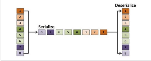
Figure 1 Example diagram showing serialization and deserialization (Image source: Texas Instruments)
With all of this in mind, let’s look at the limitations of parallel data transmission, and then I’ll discuss some of the salient SerDes concepts.
Why is serial communication preferred over parallel communication?
One of the more immediate disadvantages of parallel transmission is the number of conductors involved. If you’re still working in an 8-bit world, then using a set of interconnects might seem reasonable relative to the benefits of simple, simultaneous data transmission; however, as bus widths extend into the 16- or 32-bit range, the PCB layout task becomes increasingly inefficient and difficult to manage. The problem can become even more severe when you must not only move data from one component to another, but also from one PCB to another.
Furthermore, each of these parallel data lines is a concern for more than just the layout and routing personnel. Tightly spaced wires or PCB traces (as shown in Figure 2) are susceptible to crosstalk, especially with the high-energy logic transitions characteristic of digital signals, and larger sets of conductors are more difficult to shield from ambient electromagnetic interference (EMI).
When traces are lines in a schematic, they have perfect electrical isolation, but on a real PCB, they capacitively couple with nearby traces and plane layers.
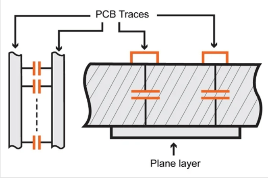
Figure 2 When traces are lines in a schematic, they have perfect electrical isolation, but on a real PCB, they capacitively couple with nearby traces and plane layers
With serial, a few interconnects are enough to transmit a data word of any bit width, and you reduce the likelihood of spurious logic transitions that would corrupt the data or require retransmission, degrading the communication quality.
In theory, parallelism does allow faster data transmission, but even this advantage is more incidental than it may initially appear. Longer traces or wires mean that the signal will take more time to propagate from transmitter to receiver, and as data rates increase, it becomes more important to equalize delays across the bus by matching trace lengths. Trace length matching for a high-speed 32-bit bus is not a trivial matter – if I were doing the layout, this would be a very strong argument in favor of serialization/deserialization. Figure 3 shows an example of bending, which can be helpful if you need to equalize trace lengths, but is less helpful when you are trying to minimize board area.
An example of a bent trace
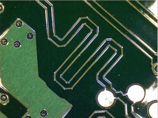
Figure 3 An example of a bent trace
Another problem with high-speed parallel buses is excessive power consumption. Serialization can reduce power consumption by converting standard logic signals to low-voltage differential signals.
What is SerDes? Overview of SerDes Functions and Features
SerDes is a process involving two separate circuit blocks: In its basic form, a serializer converts data represented by multiple simultaneous digital signals (such as output by a microprocessor or ASIC) into a time sequence of logic levels that propagate along one conductor. A deserializer converts this time sequence of logic levels back into a set of signals that propagate simultaneously along multiple conductors.
Beyond this basic function, there are various details and additional features to a SerDes implementation.
Multiple Serial Conductors
Parallel-to-serial conversion does not necessarily compress multiple conductors into one conductor. More generally, the goal of serialization is to significantly reduce the number of conductors.
First, a single serial communication line typically requires two physical conductors because many serial interfaces, such as RS-485 and USB, use differential signaling. In addition, the optimal balance between throughput and interface complexity may require multiple serial channels. For example, in the block diagram of Figure 4 below, from the datasheet for TI’s SN65LVDS95 LVDS serializer, 21 bits of parallel data are converted into three separate serial output streams.
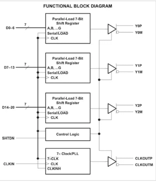
Figure 4 Functional block diagram of the SN65LVDS95 serializer from the datasheet. Image courtesy of Texas Instruments
Clock Multiplication
If the serializer receives parallel words at a specific frequency, it must increase the output bit rate in order to match the output word rate to the input word rate. Since serial transmission is more suitable for high bit frequencies than parallel transmission, serialization does not need to reduce throughput. As shown in the figure above, a phase-locked loop (PLL) can be used to multiply the input clock according to the compression factor achieved in the parallel-to-serial conversion.
Tx/Rx Synchronization
Like any digital communication interface, SerDes requires some synchronization mechanism to ensure that the receiver knows how to sample and interpret the incoming logic levels. Some systems, including the one shown in the figure above, send a clock signal along with the data.
A deserializer can also derive synchronization from an incoming serial bit stream: a PLL can lock onto the bit stream and generate a sampling clock. However, if the incoming signal has insufficient transition density, the PLL will drift. For example, a sensor signal might saturate at the positive supply rail and be digitized and serialized as a long sequence of logic high bits. To prevent problems associated with low transition density, you can combine a SerDes system with a standard (such as 8b/10b) or homemade encoding scheme.
Transmission Media
Transmitting parallel data as serial data gives you physical transmission options that would otherwise be unfeasible. Even if all your signals are on the same PCB and all are routed using ordinary traces, serialization can greatly facilitate board layout. If you are moving data from board to board, module to module, or system to system, you may prefer to use coaxial cable or optical links. If you have serial data, you can upgrade from ordinary wires to coaxial cable or optical fiber.
Get the Benefits of SerDes
SerDes have become an integral part of digital circuits. The extremely high data rates required for video interfaces, telecommunications interconnects, and various other applications cannot be similarly achieved using parallel transmission.