How to Optimize Thermal Management with Heat Sinks and Gap Fillers
Good thermal management is important to ensure the performance and reliability of electronic devices. It’s simple in concept, starting with removing excess heat from the source and distributing it over a larger area for effective heat dissipation and cooling. But in many cases, it’s challenging to implement.
The surfaces of heat-generating components are often not smooth enough to provide the low thermal impedance required for good heat transfer. Adding to the thermal management challenge, components that need cooling may be deep within the system, further complicating the removal of potentially damaging heat.
Thermal pastes and greases can be used to improve thermal conductivity, but achieving the necessary coverage to ensure good heat transfer and avoiding over-application that can cause contamination or shorts on board traces can be tricky. Also, thermal pastes and greases cannot dissipate heat laterally from the source.
However, designers have a variety of thermal interface materials (TIMs) to choose from, including gap fillers and heat sinks, to provide the consistent low thermal impedance required for effective heat transfer while eliminating any contamination issues. To meet specific system needs, TIMs can be constructed to transfer heat vertically or laterally. TIMs are available in a variety of thicknesses to meet application-specific requirements, with mechanical stability and good reliability at higher operating temperatures. TIMs also provide high electrical isolation and are easy to apply.
This article will review thermal management and provide general TIM selection guidelines. It will then introduce several TIM options from Würth Elektronik and explore the applications and design considerations for each.
What is a TIM?
TIMs are placed between a heat source and a cooling component to improve thermal coupling and heat flow. Two factors increase the efficiency of thermal coupling. The first is that the TIM is able to conform to microscopic surface irregularities, eliminating any insulating air that reduces interfacial thermal conductivity (Figure 1). Second, the TIM has the thermal conductivity required to effectively transfer heat from the source to the cooling component. Thermal conductivity, K, is measured in W/mK. It is measured using ASTM D5470, “Standard Test Method for Thermal Transmission Properties of Thermally Conductive Electrical Insulation Materials.”
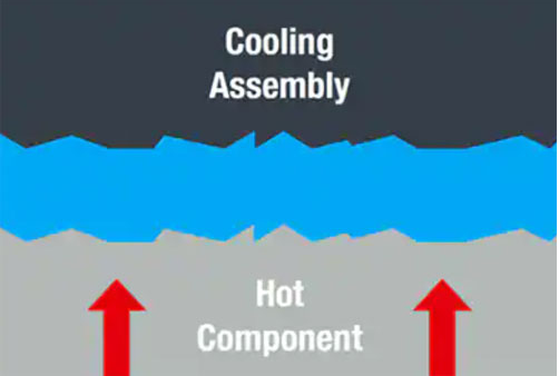
Figure 1: TIMs (blue) are used to fill microscopic irregularities on the surfaces of components and cooling assemblies to improve thermal coupling. (Image source: Würth Elektronik)
In addition to thermal conductivity, there are several factors to consider when selecting a TIM:
· Operating temperature range is important, as various TIMs have different temperature ranges.
· The distance between the mating surfaces and whether the TIM needs to be compressed to provide optimal thermal transfer.
· The ability of the TIM to withstand compression pressure.
· Some TIMs have adhesives applied to their surfaces to allow for mechanical attachment.
· Like some materials, the electrical insulation properties of TIMs can be used to provide electrical isolation.
· Some TIMs are standard with no minimum order quantity and no tooling fees, while others are custom shapes that can be optimized for specific application requirements.
Gap Filler Material Selection
WE-TGF Silicone Gap Filler is a general-purpose material designed for low-stress applications requiring electrical isolation, where the TIM is compressed to 10% – 30% of its thickness. Exceeding the recommended compression may cause the silicone oil to expel, shorten the material’s life expectancy, and potentially contaminate the printed circuit board (pc board). These TIMs are designed to be used between two mechanically fixed surfaces as there is no additional adhesive other than the natural tack. Thicknesses range from 0.5 to 18 mm with thermal conductivities of 1 to 3 W/mK. Thicknesses of 0.5 to 3 mm support higher thermal conductivities (Figure 2).
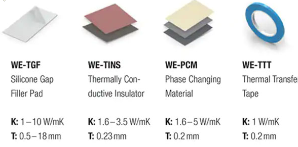
Figure 2: Würth’s thermally conductive gap filler materials meet a variety of application needs. (Image source: Würth Elektronik)
For example, part number 40001020 is a 400 x 200 mm gasket with a 2 mm thickness, a K value of 1 W/mK, and a dielectric strength or electrical breakdown rating (EBR) of 8 kV/mm. The soft and electrically insulating properties of WE-TGF gap filler materials make them suitable for use between one or more electronic components and a cooling assembly (Figure 3).
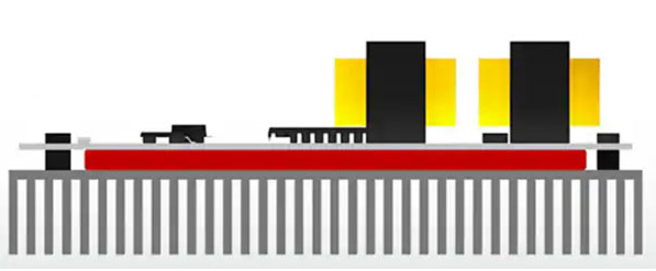
Figure 3: Silicone elastomer gap filler pads are designed to fill gaps between one or more electronic components and a cooling assembly such as a heat sink, cold plate, or metal enclosure. (Image source: Würth Elektronik)
For thermal management applications that require electrical isolation and a thinner profile, designers can use WE-TINS thermally conductive silicone insulators with K values of 1.6 to 3.5 W/mK and a thickness of 0.23 mm. Part number 404035025 has a K value of 3.5 W/mK and an EBR of 6 kV/mm. Like all parts in the WE-TINS series, 404035025 uses a combination of thermally conductive silicone rubber and a fiberglass mesh. The mesh adds mechanical strength and is resistant to puncture and shearing. Due to the mechanical properties of the structure, these TIMs can be compressed as needed and have high tensile strength.
Thermally conductive phase change materials and thermal transfer tapes are thinner, with a profile thickness of only 0.02 mm. For example, the phase change TIMs in the WE-PCM series change from solid to liquid at a specific temperature, providing a completely wetted interface without any overflow or run-off. These materials are designed for use in high-performance integrated circuits or power components and cooling assemblies. For example, part number 402150101020 measures 100 mm2, has adhesive on both sides, a K value of 5 W/mK, an EBR of 3 kV/mm, and a phase transition temperature of 55 degrees Celsius (°C).
WE-TT thermal transfer tape is a double-sided adhesive that mechanically fixes two contact surfaces. It has a K value of 1 W/mK, an EBR of 4 kV/mm, and is designed for low-stress applications. The tape is available in 25 m lengths and widths of 8 mm (part number 403012008) and 50 mm (part number 403012050).
Graphite Thermal Solutions
TIMs based on synthetic graphite have the highest levels of thermal conductivity (Figure 4). Part number 4051210297017 in the WE-TGS series is a synthetic graphite heat sink that measures 297 x 210 mm, has a K value of 1800 W/mK, and does not provide electrical isolation. These graphite sheets combine high thermal conductivity with low weight and thickness (0.03 mm) for applications ranging from high-power semiconductor modules to handheld devices.
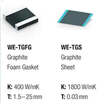
Figure 4: Graphite heat sinks have high thermal conductivity and come in a variety of sizes with a thickness of only 0.03 mm. (Image source: Würth Elektronik)
The WE-TGFG series combines graphite sheets and foam pads to form a unique thermal management solution with a K value of 400 W/mK and an EBR of 1 kV/mm. The product can be made into a long pad that acts as a heat sink, transferring heat laterally from the source to a cooling component located in another part of the system (Figure 5). For example, part number 407150045015 is 45 mm long, 15 mm wide, and 1.5 mm thick and can be used in applications that require gap filling and lateral heat transfer.
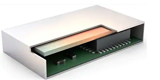
Figure 5: A TIM placed on top of a heat-generating component can act as a heat sink, transferring heat from the component laterally. (Image source: Würth Elektronik)
To achieve higher thermal conductivity with a silicone pad such as WE-TGF gap filler material, the silicone pad needs to be made thinner. Designers can fill gaps up to 25 mm with a WE-TGFG TIM, which has much higher thermal conductivity than silicone pads, and WE-TGFG parts can be manufactured in custom geometries to fit non-planar spaces (Figure 6).
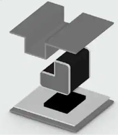
Figure 6: Graphite foam pads (center) can be manufactured in a variety of geometries and used to connect heat sources (bottom) and non-planar heat sinks (top). (Image source: Würth Elektronik)
Combining TIMs for Higher Performance
TIMs can be combined to provide higher performance. For example, a WE-TGS graphite heat sink can be combined with a WE-TGF silicone gap filler material to improve cooling of the entire assembly by using a heat sink with a footprint that exceeds the heat source (Figure 7).
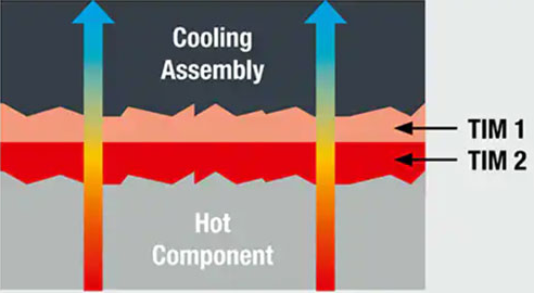
Figure 7: Combining a WE-TGS graphite heat sink (TIM 1) with a WE-TGF silicone gap filler material (TIM 2) allows for a heat sink that is larger than the footprint of the hot component, improving cooling performance. (Image source: Würth Elektronik)
General Application Guidelines
Regardless of which TIM or combination of TIMs is used, there are some general application guidelines that designers need to consider:
· Component and cooling assembly surfaces need to be clean and dry. A lint-free cotton swab or cloth and isopropyl alcohol should be used to remove any surface contamination.
· When using a TIM that requires compression, the material should be compressed evenly across the entire surface. If pressure is applied above the specified level, the material will fail.
· All bubbles and/or gaps in the surface must be eliminated to achieve optimal thermal conductivity.
· The TIM operating temperature must be able to accommodate the ambient temperature and the temperature rise of the component being cooled.
Summary
Thermal management is a common problem in electronic system design. As mentioned above, designers can use TIMs made of a variety of materials, including silicone, phase change materials, graphite, and foam pads. Using TIMs can provide the consistent low thermal impedance required for effective heat transfer while eliminating any contamination issues that may occur when using thermal paste or grease.
While thermal paste and grease can only transfer heat vertically, designers can choose between gap-filling TIMs that transfer heat vertically or heat sinks that transfer heat horizontally. Finally, many TIMs have no minimum order quantity restrictions or tooling fees, making them an economical choice for thermal management designs.