
How to improve the appearance quality of PCB solder mask
I. Introduction
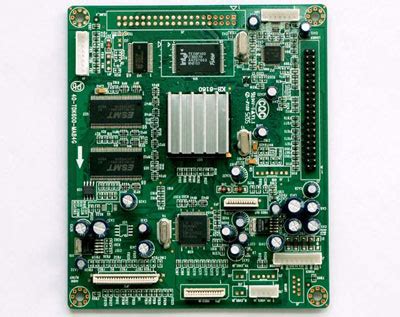
When people talk about the development trend of printed circuit boards, they often think that printed circuit boards are developing in the direction of high precision, high density and high reliability, which is the development trend. But on the other hand, users are becoming more and more stringent in the appearance requirements of printed circuit boards.
Solder mask is like the “outer coat” of printed circuit boards. In addition to requiring it to have a certain thickness and hardness, and the solvent resistance test and adhesion test meet the standards, it also requires its surface color to be uniform and glossy (currently domestic customers generally require the brighter the better), no garbage on the surface, and no extra marks.
It can be said that the appearance quality of solder mask is not only a reflection of the technical level and management level of an enterprise, but also directly affects the “orders” of the enterprise. Therefore, how to improve the appearance quality of solder mask on printed circuit boards has become a topic that every printed circuit board factory needs to solve. Based on my actual experience, I will talk about how to improve its appearance quality from the four aspects of solder mask screen printing, exposure, development and post-curing.
2.Factors affecting the appearance quality of solder mask
(1)Screen printing:
During the screen printing process of photosensitive solder mask ink, the flatness of the scraper, the purity of the screen printing environment, the screen sealing tape used during screen printing, the screen printing pressure of the ink, and the brush plate before screen printing will all affect the appearance quality. According to the actual production situation, the factors with the greatest impact are the first three. Uneven scraper is easy to produce scraper marks on the surface of solder mask; insufficient purification of the screen printing room is easy to produce garbage on the surface of solder mask; improper use of screen sealing tape is easy to dissolve the glue in the solvent of the ink and produce surface glue particles.
(2)Exposure:
During the exposure process of solder mask ink, since the solder mask has not been completely cured, the solder mask film and the solder mask are easily marked when they stick together. This is the main reason affecting the appearance quality of solder mask.
(3)Development:
At present, solder resist ink development generally adopts horizontal transfer development. Since the solder resist has not been completely cured, the driving wheel and pressure wheel of the developer are easy to damage its surface, resulting in roller marks, thus affecting the appearance quality of the solder resist. In addition, incorrect exposure energy will also affect the glossiness of the solder resist, but this can be controlled by the optical wedge table.
(4)Post-curing:
Uneven temperature during post-curing of solder resist can easily cause uneven color of solder resist. When the temperature is too high, it may even cause local yellowing and blackening, affecting the appearance of solder resist.
3.Improve the appearance quality of solder resist from four aspects
(1)Silk screen printing:
1.1 When silk screen printing solder resist ink, due to the uneven surface of the silk screen, after a period of silk screen printing, the scraper surface will become uneven, so that scraper marks will be left on the surface of the solder resist. Therefore, the operator must pay attention to the surface condition at any time. Once the scraper mark is found, the scraper should be re-grinded immediately to ensure its flatness.
1.2 We conducted parallel tests to solve the problem of surface particles of solder mask.
We selected two different tapes for screen sealing and used two solder mask inks for screen printing to observe the surface particles, as shown in Table 1.
Table 1 Compatibility of ink and tape
Tape
Tape B
Ink A Particles appeared 2 minutes after the ink and tape came into contact. Basically no particles appeared
Ink B Particles appeared about 30 minutes after the ink and tape came into contact. Basically no particles appeared
From the above test results, it can be seen that tape A and ink B have a better matching effect, and tape B can be matched with both ink A and ink B, but the cost of tape B is 5 times that of tape A. Therefore, in actual production, attention must be paid to the compatibility of solder mask ink and screen sealing tape to avoid the generation of surface particles.
1.3 In order to obtain printed boards with good appearance quality, the purity of the screen printing room environment plays a key role.
All places in contact with the printed circuit board (including countertops, screen frames, blotting paper, screen sealing tape, etc.) and the printed circuit board itself must be dusted with dust removal rollers. The turnover vehicle must be clean and dedicated to the clean room. Operators must wear special work clothes and work hats when entering the clean room, and take air showers as required. At the same time, it is also necessary to protect the air purification around the entire factory. If conditions permit, water can be sprinkled around the factory regularly for dust removal.
(2)Exposure:
How to solve the problem of sticking to the negative film during solder mask ink exposure is the key to improving the appearance quality of the printed circuit board. This mainly needs to be considered from the equipment. First of all, it is necessary to ensure that the temperature of the glass plate surface on the frame after continuous exposure does not exceed 30°C. If it is an air-cooled low-power exposure machine (less than 7KW), the exposure time is long, and the surface temperature of the glass plate will rise quickly. At this time, cooling measures (such as blowing cold air, heat insulation, etc.) should be taken to ensure that the surface temperature of the glass plate does not exceed 30°C. Secondly, the correct vacuum degree must be controlled. Too high a vacuum degree will cause the negative film to stick to the solder mask, causing negative film marks. By testing different vacuum ranges (see Table 2), the results show that the best effect is achieved when the vacuum is controlled at 70″80%.
Table 2 Effect of vacuum on viscosity film phenomenon
Vacuum 60% 70% 80% 90%
Film sticking condition No film sticking, but ghosting occurs during development No film sticking, normal development No film sticking, normal development The film sticks
Finally, it is worth mentioning that the MYLAR film on the exposure frame must be dedicated to the exposure machine, and it is best to use a flat film (rather than a convex and concave film for dry film exposure) to reduce the impact of the film on the solder mask.
3.Development:
The solder mask surface has not been completely cured during development, and it is easy to leave roller marks, so it should be considered from the equipment. First, the transmission roller must be made of soft materials or in the roller jacket, soft PVC “O” ring, and the pressure roller and squeeze roller should be made of soft rubber rollers; secondly, the stability of the entire transmission system must be ensured; finally, the pressure roller and squeeze roller of the development section should be cleaned regularly to remove the dirt stuck on the roller, so as to prevent the generation of roller marks.
4.Post-curing:
Post-curing process The main thing is to ensure the uniformity of the oven temperature. The temperature uniformity of the oven should be tested regularly. Generally, the temperature of 9 points (8 vertices and one center point) should be measured in the working state, and the value difference should not exceed 5°C. In addition, regulations should be made for the loading amount of each oven and the placement direction of the boards to avoid uneven heating of the solder mask due to poor hot air circulation, which will make the solder mask yellow and have a poor appearance.
5.Conclusion
To improve the appearance quality of the solder mask of the printed circuit board, comprehensive control is required from the aspects of process methods, raw materials, equipment, and operator’s process discipline, especially the parameters of the processes such as screen printing, exposure, development, and post-curing should be strictly monitored. In this way, the appearance quality of the solder mask of the printed circuit board can fully satisfy the customers.