Application of chain code table and line segment table in PCB hole detection
Automated optical inspection (AOI) is a visual inspection method that has emerged in recent years. It uses CCD to obtain images and judges defects and faults through computer processing and analysis comparison. The application of AOI on PCB board production lines has the advantages of fast detection speed, short programming time, and intelligent detection and control of images in large quantities. With the development of industrial technology, the requirements for the aperture size of PCB boards are becoming more and more precise, and the requirements for mass production of machines are also getting higher and higher. This article comes from a project of a company that produces hole counting machines.
The technical requirements are that the minimum radius of PCB holes is 0.2mm, and there are up to 2,000 circular holes on each PCB board. The total processing time is required to be no more than 10s. The center of the circle obtained after processing is accurate to 0.01 pixel level, and the deviation of each center of the circle from the center of the template shall not exceed 25um. If 80% of the center deviation exceeds this indicator, it is considered unqualified, and then the equipment benchmark needs to be adjusted.
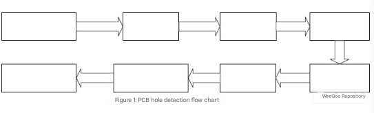
Edge refers to the set of pixels in an image whose grayscale has a step change or a roof-like change. It exists between the target and the background, between the target and the target, between the region and the region, and between the primitive and the primitive. It is very useful for image recognition and analysis. The edge can outline the contour of the target object, making it clear to the observer and containing rich information. Therefore, to obtain the hole position information, edge detection and contour tracking must be performed first. This paper uses the Freeman chain code to track the edge contour, and uses the chain code table and line segment table to store and process data. The specific flow chart is shown in Figure 1:
1 Image acquisition and preprocessing
(1) This paper uses backlight illumination and a high-resolution camera to obtain high-contrast and high-quality images.
The image resolution is 409*096. The quality of the image source is very important, which will directly affect the effect of subsequent image processing.
(2) The median filter is used to smooth the image.
Its purpose is to minimize or eliminate the influence of noise and improve image quality. Under certain conditions, median filtering can overcome the blurring of image details caused by linear filters such as minimum mean square filtering and mean filtering, and is most effective against filter pulse interference and image scanning noise. For the images involved in this article, which are the hole detail defects of the PCB board, median filtering is more appropriate. Its advantage is that it can eliminate noise without destroying the edge of the image.
(3) Use OSTU (maximum between-class variance method) for threshold segmentation.
This method is simple, stable and effective. It is a binarization method that automatically selects the threshold based on the minimum function and the principle of square multiplication. The idea is to divide the image histogram into two groups with a certain grayscale. When the variance of the two groups is the largest, this grayscale is determined as the optimal threshold.
2 Use chain code table and line segment table to describe the data results of the image
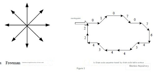
(1) Use Freeman chain code contour tracking Freeman chain code is divided into eight-connected and four-connected chain codes.
The eight-connected chain code is defined by the direction of the center pixel pointing to its eight neighbors, and the four-connected is defined by the direction of the center pixel pointing to its four neighbors, with values ranging from 0 to 3. This paper uses eight-connected chain code, as shown in Figure 2 below. The eight-connected chain code rotates clockwise. Every 45 degrees of clockwise rotation, the chain code value decreases by 1; when the chain code value is increased by 4, the direction is reversed, and when it is increased by 8, it returns to the original direction. When the chain code value exceeds 8 or is less than 0, the modulo 8 operation is used to remove or add 8.
(2) Application of chain code table
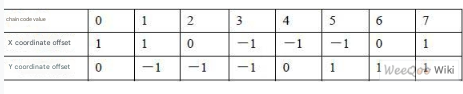
For the tracking of a single hole in a PCB board, this paper uses the Freeman chain code method to obtain the boundary chain code of the target object. When a certain point is searched as the gray level of the target body, this point is the boundary point of the target body. If this point has not been encoded, then this point is the starting point of a certain hole. From this point, the Freeman chain code method is used to track the contour. The chain code value of each point on the boundary can be tracked, and according to the deviation value between the center point and the coordinates of each neighboring point, as shown in Table 1, the coordinates of each boundary point can be obtained from the coordinates of the starting point, which can be expressed as a two-dimensional array inc.
The specific encoding process is: let the gray level of the target object be G1 and the background gray level be G2. Search the image of the entire PCB board. When a certain point A meets the grayscale of G1, it is regarded as a boundary point. Starting from A, search the boundary of the hole position clockwise. Define the initial value as the direction of the chain code value equal to 4 to search for the next point. If the grayscale value of the next point is equal to G1, it is the next boundary point. Otherwise, the search direction rotates 45 degrees clockwise and continues to search for the point with a chain code value of 3. This is done until the first point B that meets the grayscale value equal to G1 is found. Then take B as the new boundary point and set the tracking end flag to 0. If no boundary point is found in the neighboring points, set the tracking end flag to 1, indicating that it is an isolated point.
Point B is taken as the new boundary point, and its chain code value is taken as the direction of the starting chain code.
Repeat the above tracking in the clockwise direction until the last boundary point is point A. The tracking of a single hole position map is completed, and the area is marked with color filling, indicating that it has been searched. The tracked chain code value is stored in the chain code table. This paper stores the chain code table in a one-dimensional integer array code[ ]. The contents of the subscripts 0 and 1 are the coordinates X and Y of the starting boundary point, respectively. The total number of chain codes N is stored in the unit with subscript 2. Starting from the unit with subscript 3, the chain code value of the first boundary point, the chain code value of the second boundary point, and so on are stored until the chain code value of the Nth boundary point.
3 Segment table
(1) Definition of segment table
Since the chain code table can only represent the boundary of the target body, but not the inside and outside of the boundary, the chain code table cannot represent the internal pixels of the target body. However, in fact, in addition to obtaining the boundary points and perimeter of an image, other parameters are also obtained, such as the hole center data and area that this paper focuses on. To realize the processing and calculation of internal pixels, another structure is required – the segment table.
The area can also be regarded as composed of horizontal line segments. Each line segment can be represented by its two endpoints. The endpoint table that arranges all horizontal line segments in the area smoothly by scanning is called a line segment table. Each point in the line segment table consists of two parts. The even-numbered points represent the coordinates of the left endpoint, and the odd-numbered points represent the coordinates of the right endpoint. If a structure DOT is defined to represent the line segment table, a one-dimensional array dot[ ] is used, and i represents the number of line segments, then the left endpoint of this line segment can be represented as dot[2i], and the right endpoint is dot[2i+1].
(2) Application of line segment table
The line segment table obtains the values of each line segment and its endpoints, so it is very convenient to obtain the internal pixels of the area through calculation, and to find other important parameters of the image, such as the parameters that need to be found in this article: calculate the area and center of gravity of the area; quickly fill a certain area (avoid repeated searches and improve efficiency); the shape parameter of the area, the formula is: F = L*L/4 πS
The purpose of this project is to detect the center of the circular hole, so the shape detection of the area is also particularly important. In the above formula, L is the circumference and S is the area. The shape parameter F obtained by this ratio is 1. The greater the difference from 1, the greater the difference from the shape of the circle. In order to count the number and center of the circular holes in the PCB board holes, this shape parameter can be used for judgment. If it is near 1, it can be treated as a circular hole. Otherwise, it is directly filled with a non-circular hole color mark and is not included in the result.
(3) Conversion from chain code table to line segment table
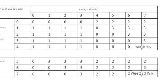
Other important parameters of the image can be obtained by using the line segment table. The conversion from chain code table to line segment table can be based on Table 2.
The specific steps are as follows:
After the chain code is converted into the table, three types are obtained: middle point, type number 0; left endpoint, type number 1; right endpoint, type number 2; singular point, type number 3. According to the data in the chain code table, the incoming chain code value and the outgoing chain code value can be known. The direction of these two can determine the type of this point. In program design, the type of point can be determined according to Table 3. If it is a left or right endpoint, its coordinates are stored in a temporary array. The singular point can be regarded as a coincidence of the same left and right points, that is, it should be stored twice, and the middle point does not need to be stored. In the line segment table, the endpoints are sorted by the size of the Y coordinate, and in the same row, they are sorted by the size of the X coordinate.
4 Experimental results
This experiment takes a screenshot of the PCB image of this project for processing. The screenshot and the processed and filled image are shown in Figure 3.
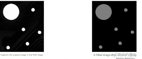
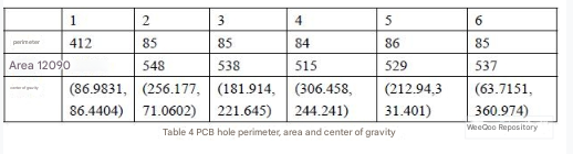
By processing the screenshots with the algorithm and program of this paper, and using the chain code table and line segment table to store data, some parameter information of the PCB hole position can be obtained, as shown in Table 4
5 Conclusion
This paper uses backlight to obtain high-quality PCB images, and uses the OSTU threshold segmentation method to stably and simply obtain the binary image of the source image, scan and perform contour tracking, and adopts the principle of tracing the next point to the right, which is more convenient and time-saving. The chain code table and line segment table are used to store data and process data, and the perimeter, area and hole position centroid of the PCB board are obtained very conveniently and accurately, successfully solving the positioning problem when punching the PCB board. This experiment was run and verified on the Visual C++ software platform, and 216 circular holes can be detected and processed within 31us, obtaining the speed and accuracy required by this project. The results prove that this method is feasible.