Summary of the inductor selection and layout of the switching power supply
The switching power supply (SMPS, Switched-Mode Power Supply) is a very efficient power converter, and its theoretical value is close to 100%, and there are many types. According to the topology, there are Boost, Buck, Boost-Buck, Charge-pump, etc.; according to the switch control method, there are PWM, PFM; according to the type of switch tube, there are BJT, FET, IGBT, etc. This discussion focuses on the PWM control Buck and Boost types commonly used in data card power management.
The main components of the switching power supply include:
input source, switch tube, energy storage inductor, control circuit, diode, load and output capacitor. At present, most semiconductor manufacturers will integrate the switch tube, control circuit and diode into a CMOS/Bipolar process power management IC, which greatly simplifies the external circuit. Among them, the energy storage inductor, as a key component of the switching power supply, plays an important role in the performance of the power supply, and is also the focus of product design engineers and debugging.
As the size of consumer electronic devices such as mobile phones, PMPs, and data cards is developing towards a trend of being light, thin, compact, and fashionable, this is in conflict with the larger capacity and larger size of inductors and capacitors required for stronger product performance. Therefore, how to reduce the size of the switching power supply inductor (the PCB area and height occupied) while ensuring product performance is an important proposition to be discussed in this article. Designers will have to make a tradeoff between circuit performance and inductor parameters.
Summary of inductor selection and layout of switching power supplies
Everything has two sides, and switching power supplies are no exception.
A bad PCB layout design will not only reduce the performance of the switching power supply, but also strengthen EMC, EMI, ground bounce, etc. The issues that should be paid attention to and the principles to be followed when laying out the switching power supply are also another important proposition to be discussed in this article.
1.The role of common-mode inductors
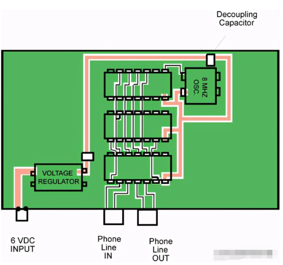
Common-mode inductors are an electronic component widely used in switching power supplies, mainly used to suppress common-mode noise at the input end of the power supply. When interference occurs at the power input, the common-mode inductor will filter out these interference signals to ensure the stability and reliability of the power output.
2.Principles for selecting copper wire
In switching power supplies, copper wire is an important component connecting the common-mode inductor and the power input. Generally speaking, the selection of copper wire should comply with the following principles:
3.The diameter should be moderate
The diameter of the copper wire should not be too thin, otherwise it will increase the resistance and inductance of the line, resulting in increased ripple and noise at the power output. However, the diameter should not be too thick, otherwise it will increase the cost and space occupied by the line.
4.The length should be appropriate
The length of the copper wire should be as short as possible, which is conducive to reducing the resistance and inductance of the line and improving the efficiency and stability of the power supply. However, the length should not be too short, otherwise it will affect the layout and connection of the line.
5.The direction should be reasonable
The direction of the copper wire should be designed according to the layout and connection method of the power supply to minimize mutual interference and coupling of the lines. Common directions include straight lines, bends, circles, etc., which should be selected according to actual conditions.
6.Layout method of copper wire
In switching power supply, the layout of copper wire is one of the key factors affecting the performance of power supply. Here are some common layout methods:
7.Use symmetrical layout
Symmetrical layout is a commonly used copper wire layout method, which can reduce the interference and coupling of the line. The specific method is to place the common mode inductor and the power input terminal at both ends of the layout, and connect them with relatively short copper wires.
8.The arrangement method should be reasonable
The arrangement method is also one of the important factors affecting the layout of copper wire. Generally speaking, copper wires can be arranged in parallel, staggered, and staggered ways to reduce the mutual influence and interference of the lines.
9.Add shielding layer
In some high-demand applications, a shielding layer can be added around the copper wire to reduce interference and electromagnetic leakage. Common shielding materials include aluminum foil, copper foil, metal mesh, etc.

