Flexible Circuit Boards: A Comprehensive Guide to Design, Manufacturing, and Applications
Flexible circuit boards, also known as flex circuits or FPCs (Flexible Printed Circuits), have become an integral part of modern electronics due to their ability to bend, twist, and conform to complex shapes. Unlike traditional rigid PCBs, flexible circuits are made from thin, flexible materials such as polyimide or polyester, enabling them to fit into compact and irregular spaces. This unique characteristic makes them ideal for applications ranging from consumer electronics to aerospace systems. This article provides a comprehensive guide to flexible circuit boards, covering their design principles, manufacturing processes, advantages, challenges, and applications.
1. Introduction to Flexible Circuit Boards
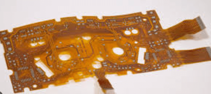
Flexible circuit boards are a type of PCB that uses flexible substrate materials, allowing them to bend and flex without breaking. They consist of conductive traces, typically made of copper, laminated onto a flexible insulating material. Flexible circuits can be single-sided, double-sided, or multilayer, depending on the complexity of the design. They are often used in applications where space and weight are critical, such as wearable devices, medical equipment, and automotive electronics.
2. Design Principles for Flexible Circuit Boards
Designing flexible circuit boards requires careful consideration of mechanical, electrical, and thermal factors. Key design principles include:
2.1 Material Selection
The choice of materials is critical for the performance and reliability of flexible circuits. Common materials include:
- Substrate: Polyimide is the most commonly used substrate material due to its excellent thermal stability, flexibility, and mechanical strength. Other materials, such as polyester, are used for less demanding applications.
- Conductive Layers: Copper is the most common conductive material due to its excellent electrical conductivity and flexibility. Adhesive or adhesive-less copper layers can be used, depending on the application.
- Coverlay: A protective layer, typically made of polyimide, is applied over the conductive traces to provide insulation and mechanical protection.
2.2 Bend Radius
The bend radius is the minimum radius at which a flexible circuit can be bent without causing damage. Key considerations include:
- Material Thickness: Thicker materials require a larger bend radius.
- Layer Count: Multilayer flexible circuits require a larger bend radius than single or double-layer circuits.
- Dynamic vs. Static Flexing: Dynamic flexing (repeated bending) requires a larger bend radius than static flexing (one-time bending).
2.3 Trace Routing
Trace routing on flexible circuits requires careful consideration of mechanical stress and electrical performance. Key guidelines include:
- Avoid Sharp Corners: Use curved traces instead of sharp corners to reduce stress and prevent cracking.
- Minimize Trace Width Variations: Consistent trace widths help distribute stress evenly and improve reliability.
- Use Teardrops: Add teardrops at the junction of traces and pads to reduce stress and prevent cracking.
2.4 Stiffeners
Stiffeners are rigid materials, such as FR-4 or aluminum, added to specific areas of the flexible circuit to provide mechanical support. Key considerations include:
- Component Mounting: Stiffeners are often used in areas where components are mounted to provide stability.
- Connector Areas: Stiffeners can be added near connectors to prevent flexing and ensure reliable connections.
2.5 Thermal Management
Thermal management is critical for flexible circuits, especially in high-power applications. Key considerations include:
- Thermal Vias: Use thermal vias to transfer heat from components to the opposite side of the circuit.
- Copper Pour: Increase the copper area around heat-generating components to improve heat dissipation.
- Heat Sinks: Integrate heat sinks or cooling systems for high-power components.
3. Manufacturing Processes for Flexible Circuit Boards
The manufacturing of flexible circuit boards involves several specialized processes to ensure the desired electrical, mechanical, and thermal properties. Key manufacturing steps include:
3.1 Material Preparation
The flexible substrate is prepared by cleaning and laminating the conductive layers. Adhesive or adhesive-less copper layers can be used, depending on the application.
3.2 Circuit Patterning
The conductive traces are patterned onto the substrate using photolithography or laser direct imaging (LDI). The excess copper is then etched away, leaving the desired circuit pattern.
3.3 Coverlay Application
A protective coverlay is applied over the conductive traces to provide insulation and mechanical protection. The coverlay is typically made of polyimide and is laminated onto the circuit using heat and pressure.
3.4 Drilling and Plating
Holes are drilled through the flexible circuit to create vias and through-holes. These holes are then plated with copper to establish electrical connections between layers.
3.5 Surface Finishing
A surface finish, such as electroless nickel immersion gold (ENIG) or immersion silver, is applied to protect the copper traces and enhance solderability.
3.6 Cutting and Forming
The flexible circuit is cut to the desired shape and formed into the final configuration. Laser cutting or die cutting is typically used for precision.
3.7 Testing and Inspection
The finished flexible circuit undergoes rigorous testing and inspection to ensure electrical performance, mechanical stability, and reliability. Common tests include electrical continuity testing, impedance testing, and thermal imaging.
4. Advantages of Flexible Circuit Boards
4.1 Space and Weight Savings
Flexible circuits can be bent and folded to fit into compact spaces, reducing the overall size and weight of the electronic device.
4.2 Improved Reliability
Flexible circuits have fewer interconnects than traditional rigid PCBs, reducing the risk of connection failures and improving reliability.
4.3 Enhanced Design Flexibility
Flexible circuits can be designed to fit complex shapes and configurations, enabling innovative product designs.
4.4 Reduced Assembly Costs
Flexible circuits can reduce assembly costs by eliminating the need for connectors and cables, simplifying the assembly process.
5. Challenges of Flexible Circuit Boards
5.1 Complexity
Flexible circuits are more complex to design and manufacture than traditional rigid PCBs, requiring specialized knowledge and equipment.
5.2 Cost
The additional materials and manufacturing processes increase the cost of flexible circuits compared to rigid PCBs.
5.3 Mechanical Stress
Repeated flexing can cause mechanical stress and lead to failure if the circuit is not designed properly.
6. Applications of Flexible Circuit Boards
6.1 Consumer Electronics
Flexible circuits are used in smartphones, tablets, and wearable devices to enable compact and lightweight designs.
6.2 Medical Devices
Flexible circuits are used in medical devices, such as hearing aids, pacemakers, and imaging systems, where reliability and flexibility are critical.
6.3 Automotive
Flexible circuits are used in automotive electronics, such as dashboard displays, sensors, and lighting systems, to withstand vibration and harsh environments.
6.4 Aerospace
Flexible circuits are used in aerospace systems, such as satellites and avionics, where weight and reliability are critical.
6.5 Industrial Equipment
Flexible circuits are used in industrial equipment, such as robotics and automation systems, to enable compact and reliable designs.
7. Emerging Trends in Flexible Circuit Boards
7.1 Stretchable Circuits
Stretchable circuits are being developed for applications that require extreme flexibility, such as wearable health monitors and soft robotics.
7.2 3D Printing
3D printing technology is being explored for creating flexible circuits with complex geometries and integrated components.
7.3 Advanced Materials
New materials, such as conductive polymers and nanomaterials, are being developed to improve the performance and reliability of flexible circuits.
8. Conclusion
Flexible circuit boards offer unique advantages in terms of space savings, design flexibility, and reliability, making them ideal for a wide range of applications. By understanding the design principles, manufacturing processes, and challenges associated with flexible circuits, engineers can create innovative and reliable electronic devices. Emerging trends, such as stretchable circuits, 3D printing, and advanced materials, are shaping the future of flexible circuit technology, offering new opportunities for innovation and performance enhancement. With careful attention to detail and adherence to industry standards, flexible circuits can deliver the reliability and performance needed to power the next generation of electronic products.