Understanding Flex PCB Current Carrying Capacity: Design Considerations and Best Practices
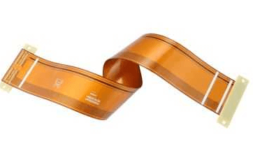
Flexible printed circuit boards (Flex PCBs) have become increasingly popular in modern electronics due to their ability to bend, twist, and conform to unique shapes. They are widely used in applications such as wearable devices, medical equipment, aerospace systems, and consumer electronics. However, one of the critical challenges in designing Flex PCBs is ensuring adequate current carrying capacity. Unlike rigid PCBs, Flex PCBs have unique mechanical and electrical properties that must be carefully considered to avoid overheating, signal degradation, or failure. This article explores the factors influencing the current carrying capacity of Flex PCBs, design considerations, and best practices to optimize performance.
What Is Current Carrying Capacity?
Current carrying capacity refers to the maximum amount of electrical current a conductor (such as a trace on a PCB) can safely carry without exceeding its temperature limits or causing performance issues. Exceeding the current carrying capacity can lead to overheating, trace damage, or even fire hazards. For Flex PCBs, this parameter is particularly important because the thin and flexible nature of the materials makes them more susceptible to thermal and mechanical stress.
Key Factors Influencing Flex PCB Current Carrying Capacity
The current carrying capacity of a Flex PCB is influenced by several factors, including trace width, thickness, material properties, and environmental conditions. Understanding these factors is essential for designing reliable and efficient Flex PCBs.
1. Trace Width and Thickness
- Trace Width: Wider traces can carry more current because they have a larger cross-sectional area, which reduces resistance and heat generation.
- Trace Thickness: Thicker copper layers (measured in ounces per square foot, e.g., 1 oz, 2 oz) increase the current carrying capacity by providing more conductive material.
2. Copper Type and Quality
- The type of copper used in Flex PCBs (e.g., rolled annealed copper or electro-deposited copper) affects its conductivity and flexibility.
- High-quality copper with minimal impurities ensures better current carrying capacity and reliability.
3. Substrate Material
- Flex PCBs use flexible substrate materials such as polyimide or polyester. These materials have different thermal and mechanical properties that influence heat dissipation and current capacity.
- Polyimide is the most common substrate due to its excellent thermal stability and flexibility.
4. Operating Temperature
- The ambient temperature and the heat generated by the PCB itself affect the current carrying capacity. Higher temperatures reduce the safe current limit due to increased resistance and thermal stress.
- Flex PCBs used in high-temperature environments must be designed with additional margin to account for thermal degradation.
5. Number of Layers
- Multilayer Flex PCBs can distribute current across multiple traces and planes, reducing the load on individual traces and improving overall current capacity.
6. Bending and Flexing
- Repeated bending or flexing can cause mechanical stress on the traces, potentially leading to cracks or breaks. This stress can also increase resistance and reduce current carrying capacity over time.
7. Environmental Conditions
- Factors such as humidity, vibration, and exposure to chemicals can affect the performance and longevity of Flex PCBs, indirectly impacting their current carrying capacity.
Calculating Current Carrying Capacity for Flex PCBs
To determine the current carrying capacity of a Flex PCB, designers can use industry-standard guidelines and formulas. One commonly used reference is the IPC-2152 standard, which provides empirical data and charts for calculating trace current capacity based on temperature rise, trace width, and copper thickness.
Key Parameters for Calculation:
- Temperature Rise: The allowable temperature increase above ambient conditions (e.g., 10°C, 20°C).
- Trace Width: The width of the trace in mils or millimeters.
- Copper Thickness: The thickness of the copper layer in ounces or micrometers.
Example Calculation:
Using the IPC-2152 charts, a 10-mil-wide trace with 1 oz copper can carry approximately 1 A of current with a 10°C temperature rise. For higher currents or lower temperature rises, the trace width or copper thickness must be increased.
Design Considerations for Maximizing Current Carrying Capacity
Designing Flex PCBs with adequate current carrying capacity requires careful planning and attention to detail. Here are some best practices to follow:
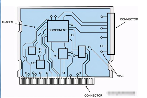
1. Optimize Trace Geometry
- Use wider traces for high-current paths to reduce resistance and heat generation.
- Avoid sharp corners in traces, as they can create hotspots and increase resistance.
2. Increase Copper Thickness
- Use thicker copper layers (e.g., 2 oz or 3 oz) for high-current applications.
- Consider using heavy copper Flex PCBs for extreme current requirements.
3. Use Multiple Layers
- Distribute current across multiple layers to reduce the load on individual traces.
- Use power and ground planes to provide low-resistance paths for high currents.
4. Minimize Bending Stress
- Design traces to run perpendicular to the bend axis to reduce mechanical stress.
- Use curved traces instead of sharp angles to prevent cracking.
5. Improve Heat Dissipation
- Incorporate thermal vias to transfer heat from high-current traces to other layers or heat sinks.
- Use materials with high thermal conductivity, such as polyimide with embedded metal cores.
6. Account for Environmental Factors
- Design for the worst-case operating conditions, including high temperatures and humidity.
- Use conformal coatings or encapsulation to protect the PCB from environmental damage.
7. Simulate and Test
- Use thermal simulation tools to predict temperature rise and identify potential hotspots.
- Perform real-world testing to validate the design under actual operating conditions.
Applications and Case Studies
Flex PCBs are used in a wide range of applications, each with unique current carrying requirements. Here are some examples:
- Wearable Devices:
- Flex PCBs in smartwatches and fitness trackers must carry low to moderate currents while withstanding repeated bending and flexing.
- Designers use thin traces with adequate width and polyimide substrates to balance flexibility and current capacity.
- Medical Equipment:
- Medical devices such as endoscopes and implantable sensors require Flex PCBs with high reliability and precise current handling.
- Multilayer designs and high-quality materials are often used to meet stringent performance standards.
- Aerospace Systems:
- Flex PCBs in aerospace applications must handle high currents while enduring extreme temperatures and vibrations.
- Heavy copper layers and advanced thermal management techniques are employed to ensure reliability.
- Consumer Electronics:
- Flex PCBs in smartphones and laptops carry currents for power distribution and signal transmission.
- Designers optimize trace geometry and use multilayer designs to meet space and performance constraints.
Challenges and Solutions
Designing Flex PCBs with adequate current carrying capacity presents several challenges, but these can be addressed with the right strategies:
- Thermal Management:
- Challenge: Heat buildup in high-current traces can cause thermal stress and failure.
- Solution: Use thermal vias, heat sinks, and materials with high thermal conductivity.
- Mechanical Stress:
- Challenge: Repeated bending can cause trace cracking and increased resistance.
- Solution: Design traces to minimize stress and use flexible materials with high fatigue resistance.
- Space Constraints:
- Challenge: Limited space in compact devices restricts trace width and thickness.
- Solution: Use multilayer designs and optimize trace routing to maximize current capacity.
- Cost Considerations:
- Challenge: High-quality materials and advanced designs can increase costs.
- Solution: Balance performance and cost by selecting materials and design techniques that meet requirements without over-engineering.
Conclusion
The current carrying capacity of Flex PCBs is a critical parameter that directly impacts their performance, reliability, and longevity. By understanding the factors that influence current capacity and following best practices in design and material selection, engineers can create Flex PCBs that meet the demands of even the most challenging applications.
As the use of Flex PCBs continues to grow in industries such as wearable technology, medical devices, and aerospace, the importance of optimizing current carrying capacity will only increase. By leveraging advanced design tools, simulation techniques, and high-quality materials, designers can push the boundaries of what is possible with Flex PCBs, enabling innovative solutions for the electronics of tomorrow.