PCB Soldering: A Comprehensive Guide
Introduction
Printed Circuit Board (PCB) soldering is a fundamental skill in electronics manufacturing and repair. It involves the process of joining electronic components to a PCB using solder, a fusible metal alloy. Proper soldering ensures reliable electrical connections and mechanical stability, which are crucial for the functionality and longevity of electronic devices. This article provides a comprehensive guide to PCB soldering, covering the basics, techniques, tools, and best practices.
1. Understanding PCB Soldering
1.1 What is Soldering?
Soldering is a process where two or more metal items are joined together by melting and flowing a filler metal (solder) into the joint. The solder has a lower melting point than the metals being joined, allowing it to create a strong bond without damaging the components.
1.2 Types of Soldering
There are two main types of soldering used in PCB assembly:
- Through-Hole Soldering: Components with wire leads are inserted into holes drilled in the PCB and soldered on the opposite side.
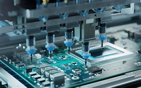
- Surface-Mount Soldering: Components are placed directly onto the surface of the PCB and soldered in place. This method is more common in modern electronics due to the miniaturization of components.
2. Essential Tools and Materials
2.1 Soldering Iron
A soldering iron is the primary tool used in soldering. It consists of a heated metal tip that melts the solder. Key features to consider when choosing a soldering iron include:
- Wattage: Typically ranges from 15W to 60W. Higher wattage irons heat up faster and maintain temperature better.
- Temperature Control: Adjustable temperature settings allow for precise control, which is essential for different types of solder and components.
- Tip Shape and Size: Different tips are suited for various tasks. Fine tips are ideal for detailed work, while broader tips are better for larger joints.
2.2 Solder
Solder is a metal alloy used to create the joint. The most common types are:
- Lead-Based Solder: Composed of tin and lead (typically 60/40 or 63/37 ratio). It has a lower melting point and is easier to work with but is being phased out due to environmental and health concerns.
- Lead-Free Solder: Made from tin, silver, and copper. It has a higher melting point and is more environmentally friendly but can be more challenging to work with.
2.3 Flux
Flux is a chemical cleaning agent used to remove oxidation from the metal surfaces and improve the flow of solder. It comes in various forms, including paste, liquid, and core within the solder wire.
2.4 Desoldering Tools
Desoldering tools are used to remove solder and components from a PCB. Common tools include:
- Desoldering Pump (Solder Sucker): A spring-loaded vacuum device that sucks up molten solder.
- Desoldering Braid (Solder Wick): A braided copper wire that absorbs molten solder when heated.
2.5 Other Tools
- Tweezers: For handling small components.
- Magnifying Glass or Microscope: For inspecting small joints and components.
- Soldering Stand: To hold the soldering iron when not in use.
- Sponge or Brass Wool: For cleaning the soldering iron tip.
3. Soldering Techniques
3.1 Preparing the Soldering Iron
Before starting, ensure the soldering iron is clean and properly tinned. Tinning involves coating the tip with a thin layer of solder to improve heat transfer and prevent oxidation.
3.2 Through-Hole Soldering
- Insert the Component: Place the component leads through the holes in the PCB.
- Bend the Leads: Slightly bend the leads to hold the component in place.
- Heat the Joint: Touch the soldering iron tip to the joint where the lead and PCB pad meet.
- Apply Solder: Feed solder into the joint until it flows evenly around the lead and pad.
- Remove the Iron: Once the solder has flowed, remove the iron and allow the joint to cool naturally.
- Trim the Leads: Use wire cutters to trim the excess lead length.
3.3 Surface-Mount Soldering
- Apply Flux: Apply a small amount of flux to the PCB pads.
- Position the Component: Use tweezers to place the component onto the pads.
- Tack One Pad: Solder one pad to hold the component in place.
- Solder Remaining Pads: Solder the remaining pads, ensuring the component is properly aligned.
- Inspect the Joints: Use a magnifying glass to inspect the joints for proper solder flow and alignment.
3.4 Desoldering
- Heat the Joint: Apply the soldering iron to the joint to melt the solder.
- Use Desoldering Tool: Use a desoldering pump or braid to remove the molten solder.
- Remove the Component: Once the solder is removed, gently pull the component from the PCB.
4. Common Soldering Issues and Solutions
4.1 Cold Joints
Cold joints occur when the solder does not melt completely, resulting in a weak and unreliable connection. This can be caused by insufficient heat or movement during cooling.
- Solution: Ensure the soldering iron is at the correct temperature and hold it steady until the solder flows properly.
4.2 Solder Bridges
Solder bridges happen when solder inadvertently connects two adjacent pads or leads, causing a short circuit.
- Solution: Use a desoldering braid to remove excess solder and reapply solder carefully.
4.3 Insufficient Solder
Insufficient solder can lead to weak joints that may break or fail over time.
- Solution: Apply enough solder to create a strong, shiny joint that covers the entire pad and lead.
4.4 Overheating
Overheating can damage components and the PCB.
- Solution: Use the correct temperature and avoid prolonged contact with the soldering iron.
5. Best Practices for PCB Soldering
5.1 Work in a Well-Ventilated Area
Soldering can produce fumes that are harmful if inhaled. Always work in a well-ventilated area or use a fume extractor.
5.2 Use the Right Temperature
Different solders and components require different temperatures. Adjust the soldering iron accordingly to avoid damage.
5.3 Keep the Iron Clean
A clean soldering iron tip ensures better heat transfer and cleaner joints. Regularly clean the tip with a sponge or brass wool.
5.4 Practice Good Hygiene
Wash your hands after soldering, especially if using lead-based solder, to avoid ingestion of harmful substances.
5.5 Inspect Your Work
Always inspect your solder joints under magnification to ensure they are properly formed and free of defects.
6. Advanced Soldering Techniques
6.1 Reflow Soldering
Reflow soldering is a process used primarily for surface-mount components. Solder paste is applied to the PCB pads, components are placed on top, and the entire assembly is heated in a reflow oven to melt the solder and form the joints.
6.2 Wave Soldering
Wave soldering is used for through-hole components. The PCB is passed over a wave of molten solder, which solders the components in place.
6.3 Selective Soldering
Selective soldering is used for mixed-technology PCBs that have both through-hole and surface-mount components. A selective soldering machine applies solder only to the areas that require it.
7. Safety Considerations
7.1 Electrical Safety
Always unplug the soldering iron when not in use and avoid touching the hot tip.
7.2 Fire Safety
Soldering irons can reach high temperatures and pose a fire hazard. Keep flammable materials away and use a heat-resistant mat.
7.3 Personal Protective Equipment (PPE)
Wear safety glasses to protect your eyes from solder splashes and fumes. Heat-resistant gloves can also be useful.
8. Conclusion
PCB soldering is a critical skill in electronics that requires practice and attention to detail. By understanding the basics, using the right tools and techniques, and following best practices, you can create reliable and durable electronic assemblies. Whether you are a hobbyist or a professional, mastering PCB soldering will enhance your ability to build and repair electronic devices effectively.