Through-Hole PCB Assembly: A Comprehensive Guide
Introduction
Printed Circuit Boards (PCBs) are the backbone of modern electronics, providing the necessary platform for mounting and interconnecting electronic components. Among the various methods of assembling PCBs, Through-Hole Technology (THT) remains a widely used and reliable approach, particularly for applications requiring robust mechanical connections and high reliability. This article delves into the intricacies of through-hole PCB assembly, exploring its advantages, processes, challenges, and future prospects.
1. Understanding Through-Hole Technology
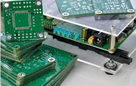
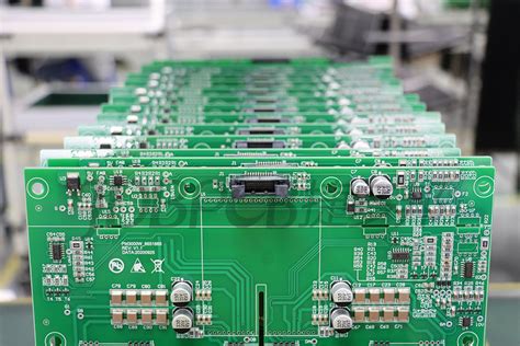
Through-hole technology involves the insertion of component leads through drilled holes in the PCB, followed by soldering to secure the components and establish electrical connections. This method contrasts with Surface Mount Technology (SMT), where components are mounted directly onto the surface of the PCB.
1.1 Historical Context
Through-hole technology has been the dominant PCB assembly method since the advent of modern electronics in the mid-20th century. Its widespread adoption was driven by the need for reliable and durable connections in early electronic devices, such as radios, televisions, and military equipment. Despite the rise of SMT in recent decades, THT continues to play a crucial role in various industries.
1.2 Types of Through-Hole Components
Through-hole components come in various forms, including:
- Axial Lead Components: These components have leads extending from both ends, such as resistors, capacitors, and diodes. They are typically mounted horizontally or vertically on the PCB.
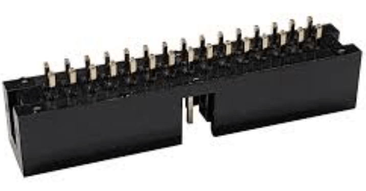
- Radial Lead Components: These components have leads protruding from one end, such as electrolytic capacitors and some types of connectors. They are usually mounted vertically.
- Dual In-line Package (DIP) Components: These include integrated circuits (ICs) with two parallel rows of leads. DIP components are widely used in through-hole assembly due to their ease of handling and reliable connections.
2. The Through-Hole PCB Assembly Process
The through-hole PCB assembly process involves several sequential steps, each critical to ensuring the quality and reliability of the final product.
2.1 PCB Design and Fabrication
The assembly process begins with the design and fabrication of the PCB. Designers use Computer-Aided Design (CAD) software to create the PCB layout, specifying the placement of through-hole components and the routing of traces. The design must account for factors such as component size, lead spacing, and thermal management.
Once the design is finalized, the PCB is fabricated. This involves etching the copper layers to create the conductive traces, drilling holes for component leads, and applying solder mask and silkscreen for protection and labeling.
2.2 Component Preparation
Before assembly, through-hole components must be prepared. This includes straightening and trimming the leads to the appropriate length. Automated machines or manual tools can perform these tasks, depending on the production volume and complexity.
2.3 Component Insertion
The next step is inserting the components into the PCB. This can be done manually for low-volume production or prototyping, or using automated insertion machines for high-volume manufacturing. Automated insertion machines, such as axial inserters and DIP inserters, can place components with high precision and speed.
2.4 Soldering
Soldering is a critical step in through-hole assembly, as it establishes the electrical and mechanical connections between the components and the PCB. The two primary soldering methods used in THT are:
- Wave Soldering: In this method, the PCB is passed over a wave of molten solder, which wets the exposed metal surfaces and forms solder joints. Wave soldering is highly efficient for high-volume production and is particularly suited for single-sided or double-sided PCBs with through-hole components on one side.
- Hand Soldering: For low-volume production, rework, or prototyping, hand soldering is often employed. Skilled technicians use soldering irons to manually solder each component lead to the PCB. Hand soldering allows for greater control and flexibility but is less efficient for large-scale production.
2.5 Inspection and Testing
After soldering, the assembled PCB undergoes inspection and testing to ensure quality and functionality. Visual inspection, automated optical inspection (AOI), and X-ray inspection are commonly used to detect soldering defects, such as cold joints, bridging, or insufficient solder.
Functional testing is also performed to verify that the PCB operates as intended. This may involve in-circuit testing (ICT), where individual components are tested for proper operation, or functional testing, where the entire PCB is tested under real-world conditions.
2.6 Cleaning and Conformal Coating
Depending on the application, the assembled PCB may be cleaned to remove flux residues and other contaminants. Cleaning methods include ultrasonic cleaning, vapor degreasing, and aqueous cleaning.
In some cases, a conformal coating is applied to the PCB to protect it from environmental factors such as moisture, dust, and chemicals. Conformal coatings can be applied via spraying, brushing, or dipping and are available in various materials, including acrylic, silicone, and urethane.
3. Advantages of Through-Hole PCB Assembly
Through-hole technology offers several advantages that make it suitable for specific applications:
3.1 Mechanical Strength
Through-hole components are mechanically robust, as their leads pass through the PCB and are soldered on the opposite side. This provides a strong mechanical connection, making THT ideal for applications subject to mechanical stress, vibration, or high temperatures.
3.2 Reliability
The through-hole assembly process creates reliable electrical connections, as the solder joints are typically larger and more robust than those in SMT. This reliability is crucial in critical applications such as aerospace, automotive, and industrial electronics.
3.3 Ease of Prototyping and Rework
Through-hole components are easier to handle and solder manually, making THT well-suited for prototyping and low-volume production. Additionally, through-hole components can be easily replaced or reworked, which is advantageous during the development and testing phases.
3.4 Compatibility with High-Power Components
Through-hole technology is often used for high-power components, such as transformers, connectors, and large capacitors, which require robust connections and heat dissipation. The through-hole design allows for better thermal management and current handling compared to SMT.
4. Challenges and Limitations of Through-Hole PCB Assembly
Despite its advantages, through-hole technology has some limitations and challenges:
4.1 Size and Weight
Through-hole components are generally larger and heavier than their SMT counterparts, leading to bulkier and heavier PCBs. This can be a disadvantage in applications where space and weight are critical, such as portable electronics and consumer devices.
4.2 Limited Component Density
The through-hole assembly process requires drilled holes for each component lead, limiting the component density on the PCB. This contrasts with SMT, where components can be placed on both sides of the PCB, allowing for higher component density and more compact designs.
4.3 Higher Manufacturing Costs
Through-hole assembly can be more labor-intensive and time-consuming than SMT, particularly for high-volume production. The need for drilling holes, inserting components, and wave soldering can increase manufacturing costs compared to SMT, which is highly automated and efficient.
4.4 Design Complexity
Designing PCBs for through-hole assembly can be more complex, as designers must account for component lead spacing, hole sizes, and thermal management. This complexity can increase the time and cost of PCB design and fabrication.
5. Future Prospects of Through-Hole PCB Assembly
While surface mount technology has become the dominant method for PCB assembly, through-hole technology continues to evolve and find relevance in specific applications.
5.1 Hybrid Assembly
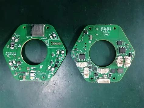
Many modern PCBs use a hybrid approach, combining both through-hole and surface mount components. This allows designers to leverage the strengths of both technologies, using through-hole components for high-power or mechanically critical parts and SMT for high-density and compact designs.
5.2 Advancements in Automation
Advancements in automation and robotics are improving the efficiency and cost-effectiveness of through-hole assembly. Automated insertion machines, robotic soldering systems, and advanced inspection technologies are reducing labor costs and increasing production speeds.
5.3 Niche Applications
Through-hole technology remains essential in niche applications where reliability and mechanical strength are paramount. Industries such as aerospace, automotive, and industrial electronics continue to rely on THT for critical components and systems.
5.4 Education and Training
As through-hole technology becomes less common in mainstream electronics, there is a growing need for education and training in THT assembly techniques. Ensuring that engineers and technicians are skilled in through-hole assembly will be crucial for maintaining the technology’s relevance in specialized applications.
Conclusion
Through-hole PCB assembly remains a vital technology in the electronics industry, offering unmatched mechanical strength, reliability, and ease of prototyping. While surface mount technology has largely supplanted THT in many applications, through-hole assembly continues to play a crucial role in specific industries and applications. As technology advances, the integration of through-hole and surface mount techniques, along with increased automation, will ensure that THT remains a valuable tool for electronics manufacturers. Understanding the processes, advantages, and challenges of through-hole assembly is essential for engineers and designers seeking to create robust and reliable electronic products.


