
PCB vs PWB: Understanding the Differences and Applications
Introduction
In the world of electronics, the terms PCB (Printed Circuit Board) and PWB (Printed Wiring Board) are often used interchangeably, leading to confusion among professionals and enthusiasts alike. While both are integral to the functioning of electronic devices, they serve distinct purposes and have unique characteristics. This article aims to clarify the differences between PCBs and PWBs, explore their respective applications, and provide a comprehensive understanding of their roles in modern electronics.
1. Definitions and Basic Concepts
1.1 Printed Circuit Board (PCB)
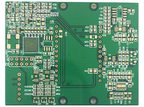
A Printed Circuit Board (PCB) is a fundamental component in electronic devices that provides mechanical support and electrical connections for various electronic components. PCBs are made from non-conductive substrates, typically fiberglass, with conductive pathways etched or printed onto the surface. These pathways, known as traces, connect different components such as resistors, capacitors, and integrated circuits (ICs) to form a functional electronic circuit.
PCBs come in various types, including single-sided, double-sided, and multi-layer boards. Single-sided PCBs have conductive traces on one side of the substrate, while double-sided PCBs have traces on both sides. Multi-layer PCBs consist of multiple layers of conductive traces separated by insulating layers, allowing for more complex circuits and higher component density.
1.2 Printed Wiring Board (PWB)
A Printed Wiring Board (PWB) is similar to a PCB in that it provides a platform for connecting electronic components. However, the term PWB is often used to describe a board that primarily serves as a wiring platform without the additional functionality of a PCB. In other words, a PWB is a simpler version of a PCB, focusing mainly on the interconnection of components rather than the integration of complex circuits.
PWBs are typically used in applications where the primary requirement is to connect components without the need for additional circuitry or signal processing. They are often found in simpler electronic devices or as part of larger systems where the main circuitry is housed on a separate PCB.
2. Historical Context
The evolution of PCBs and PWBs can be traced back to the early 20th century when the need for more efficient and reliable methods of connecting electronic components became apparent. The first PCBs were developed in the 1920s and 1930s, with the invention of the “printed wire” technique, which allowed for the mass production of electronic circuits.
During World War II, the demand for more advanced electronic systems led to the development of multi-layer PCBs, which allowed for greater complexity and miniaturization. In the post-war era, the electronics industry continued to evolve, with PCBs becoming the standard for most electronic devices.
PWBs, on the other hand, have a more modest history. They were initially used in simpler applications where the primary requirement was to connect components without the need for complex circuitry. Over time, the distinction between PCBs and PWBs has become less clear, with the terms often used interchangeably in the industry.
3. Key Differences Between PCBs and PWBs
While PCBs and PWBs share some similarities, there are several key differences that set them apart:
3.1 Functionality
The primary difference between PCBs and PWBs lies in their functionality. PCBs are designed to provide both mechanical support and electrical connections for electronic components, often incorporating complex circuitry and signal processing capabilities. PWBs, on the other hand, are primarily focused on providing a platform for interconnecting components, with less emphasis on integrating complex circuits.
3.2 Complexity
PCBs are generally more complex than PWBs, with multiple layers of conductive traces and a higher density of components. This complexity allows PCBs to support advanced electronic functions, such as signal processing, power management, and data communication. PWBs, in contrast, are simpler in design, with fewer layers and a lower component density, making them suitable for less complex applications.
3.3 Applications
PCBs are used in a wide range of electronic devices, from consumer electronics like smartphones and laptops to industrial equipment and aerospace systems. Their ability to support complex circuitry and high component density makes them ideal for applications that require advanced functionality and miniaturization.
PWBs, on the other hand, are typically used in simpler electronic devices or as part of larger systems where the main circuitry is housed on a separate PCB. Examples of PWB applications include basic electronic toys, simple control systems, and some types of sensors.
3.4 Manufacturing Process
The manufacturing process for PCBs is more complex and involves multiple steps, including the design of the circuit layout, the etching of conductive traces, and the assembly of components. Multi-layer PCBs require additional steps, such as laminating multiple layers of substrate and drilling vias to connect the layers.
PWBs, being simpler in design, have a more straightforward manufacturing process. The focus is on creating a reliable platform for interconnecting components, with less emphasis on the complexity of the circuitry. This makes PWBs more cost-effective to produce, especially for large-scale applications.
4. Advantages and Disadvantages
4.1 Advantages of PCBs
- High Functionality: PCBs can support complex circuitry and advanced electronic functions, making them suitable for a wide range of applications.
- Miniaturization: The ability to create multi-layer PCBs with high component density allows for the miniaturization of electronic devices.
- Reliability: PCBs are designed to provide reliable electrical connections, reducing the risk of circuit failure.
- Scalability: PCBs can be easily scaled to meet the requirements of different applications, from simple consumer electronics to complex industrial systems.
4.2 Disadvantages of PCBs
- Cost: The manufacturing process for PCBs is more complex and expensive, especially for multi-layer boards.
- Design Complexity: Designing a PCB requires specialized knowledge and software, which can be a barrier for small-scale projects.
- Lead Time: The production of PCBs can take longer due to the complexity of the manufacturing process.
4.3 Advantages of PWBs
- Cost-Effectiveness: PWBs are simpler to manufacture, making them more cost-effective for large-scale production.
- Ease of Design: The design process for PWBs is less complex, requiring less specialized knowledge and software.
- Quick Turnaround: The simpler manufacturing process allows for faster production times, making PWBs ideal for projects with tight deadlines.
4.4 Disadvantages of PWBs
- Limited Functionality: PWBs are not suitable for applications that require complex circuitry or advanced electronic functions.
- Lower Component Density: PWBs have a lower component density compared to PCBs, limiting their use in miniaturized devices.
- Reduced Reliability: The simpler design of PWBs may result in less reliable electrical connections, especially in high-stress environments.
5. Applications of PCBs and PWBs
5.1 Applications of PCBs
PCBs are used in a wide range of applications, including:
- Consumer Electronics: Smartphones, laptops, tablets, and other consumer devices rely on PCBs for their functionality.
- Industrial Equipment: PCBs are used in industrial control systems, automation equipment, and power management systems.
- Aerospace and Defense: PCBs are critical components in avionics, communication systems, and military equipment.
- Medical Devices: PCBs are used in medical imaging equipment, diagnostic devices, and patient monitoring systems.
- Automotive: PCBs are used in engine control units, infotainment systems, and advanced driver-assistance systems (ADAS).
5.2 Applications of PWBs
PWBs are typically used in simpler applications, such as:
- Basic Electronic Toys: PWBs are often used in simple electronic toys that require basic circuitry.
- Control Systems: PWBs are used in basic control systems for appliances, lighting, and other simple electronic devices.
- Sensors: Some types of sensors use PWBs to connect components and transmit signals.
- Prototyping: PWBs are sometimes used in the prototyping phase of electronic projects, where the focus is on testing basic functionality before moving to a more complex PCB design.
6. Future Trends and Developments
The electronics industry is constantly evolving, with new technologies and materials driving the development of both PCBs and PWBs. Some of the key trends and developments in this field include:
6.1 Miniaturization and High-Density Interconnects
As electronic devices continue to shrink in size, there is a growing demand for PCBs with higher component density and more complex circuitry. This has led to the development of advanced manufacturing techniques, such as high-density interconnect (HDI) technology, which allows for the creation of PCBs with finer traces and smaller vias.
6.2 Flexible and Rigid-Flex PCBs
Flexible PCBs and rigid-flex PCBs are becoming increasingly popular in applications where traditional rigid PCBs are not suitable. Flexible PCBs are made from flexible materials, allowing them to bend and conform to the shape of the device. Rigid-flex PCBs combine the benefits of both rigid and flexible PCBs, offering greater design flexibility and reliability in complex applications.
6.3 Advanced Materials
The development of new materials, such as high-performance substrates and conductive inks, is driving innovation in PCB and PWB manufacturing. These materials offer improved thermal management, electrical performance, and reliability, making them ideal for high-stress applications.
6.4 Internet of Things (IoT)
The growth of the Internet of Things (IoT) is driving demand for PCBs and PWBs that can support the connectivity and functionality required for IoT devices. This includes the development of low-power, high-performance PCBs for sensors, communication modules, and other IoT components.
6.5 Environmental Considerations
As environmental concerns become more prominent, there is a growing focus on developing eco-friendly PCBs and PWBs. This includes the use of lead-free materials, recyclable substrates, and manufacturing processes that minimize waste and energy consumption.
Conclusion
In conclusion, while PCBs and PWBs share some similarities, they serve distinct purposes in the world of electronics. PCBs are complex, multi-functional boards that support advanced electronic functions, while PWBs are simpler, cost-effective platforms for interconnecting components. Understanding the differences between these two types of boards is essential for selecting the right solution for a given application.
As the electronics industry continues to evolve, the demand for both PCBs and PWBs is expected to grow, driven by trends such as miniaturization, the Internet of Things, and the development of advanced materials. By staying informed about these trends and developments, professionals in the electronics industry can make informed decisions about the design and manufacture of PCBs and PWBs, ensuring that they meet the needs of today’s rapidly changing technological landscape.