Single-Sided Printed Circuit Boards: An Overview
Introduction
Printed Circuit Boards (PCBs) are the backbone of modern electronics, serving as the foundation upon which electronic components are mounted and interconnected. Among the various types of PCBs, single-sided printed circuit boards (SSPCBs) are the simplest and most cost-effective option. They are widely used in a variety of applications, from consumer electronics to industrial control systems. This article provides a comprehensive overview of single-sided printed circuit boards, covering their design, manufacturing process, advantages, limitations, and applications.
1. What is a Single-Sided Printed Circuit Board?
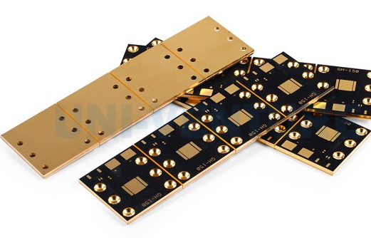
A single-sided printed circuit board is a type of PCB that has conductive traces and pads on only one side of the board. The other side is typically left bare or covered with a solder mask to protect the board from environmental factors. Single-sided PCBs are the most basic form of PCBs and are often used in simple electronic devices where the complexity of the circuit is low.
The conductive layer on a single-sided PCB is usually made of copper, which is etched to form the desired circuit pattern. The components are mounted on the non-conductive side of the board, and their leads are passed through holes in the board to make electrical connections with the copper traces on the other side.
2. Design Considerations for Single-Sided PCBs
Designing a single-sided PCB requires careful consideration of several factors to ensure that the board functions correctly and reliably. Some of the key design considerations include:
2.1. Component Placement
Since all the connections are made on one side of the board, component placement is critical in single-sided PCBs. Components should be arranged in such a way that the routing of traces is as simple and efficient as possible. This often involves placing components in a logical order, with input components on one side of the board and output components on the other.
2.2. Trace Routing
Trace routing on a single-sided PCB can be challenging due to the limited space available. Designers must ensure that traces do not cross each other, as this would create a short circuit. To avoid this, designers often use jumpers or zero-ohm resistors to bridge gaps between traces. However, excessive use of jumpers can complicate the assembly process and increase the risk of errors.
2.3. Trace Width and Spacing
The width of the traces and the spacing between them are important factors in determining the current-carrying capacity and the overall reliability of the PCB. Wider traces can carry more current, but they also take up more space. Designers must strike a balance between trace width and spacing to ensure that the board can handle the required current without causing overheating or signal interference.
2.4. Hole Size and Placement
The holes in a single-sided PCB are used to mount components and make electrical connections. The size of the holes must be carefully chosen to match the leads of the components being used. Additionally, the placement of the holes must be precise to ensure that the components fit properly and that the connections are reliable.
3. Manufacturing Process of Single-Sided PCBs
The manufacturing process of single-sided PCBs involves several steps, each of which must be carefully controlled to ensure the quality and reliability of the final product. The main steps in the manufacturing process are as follows:
3.1. Substrate Preparation
The first step in the manufacturing process is the preparation of the substrate, which is typically made of a non-conductive material such as fiberglass (FR-4). The substrate is cut to the desired size and shape, and any necessary holes are drilled.
3.2. Copper Cladding
Once the substrate is prepared, a thin layer of copper is laminated onto one side of the board. This copper layer will form the conductive traces and pads of the PCB.
3.3. Photoresist Application
A photoresist material is then applied to the copper-clad substrate. The photoresist is a light-sensitive material that hardens when exposed to ultraviolet (UV) light. A photographic film containing the circuit pattern is placed over the photoresist, and the board is exposed to UV light. The areas of the photoresist that are exposed to the light harden, while the unexposed areas remain soft.
3.4. Etching
After the photoresist has been exposed, the board is placed in an etching solution that removes the unexposed photoresist and the underlying copper. The hardened photoresist protects the copper traces and pads, leaving them intact. Once the etching process is complete, the remaining photoresist is removed, revealing the copper circuit pattern.
3.5. Drilling
Holes are drilled into the board to accommodate the leads of the components. The size and placement of the holes must be precise to ensure that the components fit properly and that the connections are reliable.
3.6. Solder Mask Application
A solder mask is applied to the board to protect the copper traces from oxidation and to prevent solder bridges from forming between closely spaced traces during the assembly process. The solder mask is typically green, but other colors are also available.
3.7. Silkscreen Printing
A silkscreen layer is printed onto the board to add labels, component identifiers, and other markings. This layer helps assemblers identify the correct placement of components and ensures that the board is assembled correctly.
3.8. Surface Finish
Finally, a surface finish is applied to the exposed copper areas to protect them from oxidation and to improve solderability. Common surface finishes include HASL (Hot Air Solder Leveling), ENIG (Electroless Nickel Immersion Gold), and OSP (Organic Solderability Preservative).
4. Advantages of Single-Sided PCBs
Single-sided PCBs offer several advantages that make them a popular choice for many applications. Some of the key advantages include:
4.1. Cost-Effectiveness
Single-sided PCBs are the most cost-effective type of PCB due to their simple design and manufacturing process. They require fewer materials and less complex equipment, which reduces the overall cost of production.
4.2. Ease of Design and Assembly
The simplicity of single-sided PCBs makes them easy to design and assemble. The single-layer design reduces the complexity of the circuit, making it easier to troubleshoot and repair if necessary.
4.3. Compact Size
Single-sided PCBs are typically smaller and lighter than double-sided or multi-layer PCBs, making them ideal for applications where space is limited.
4.4. Reliability
Single-sided PCBs are less prone to manufacturing defects and are generally more reliable than more complex PCB types. The simplicity of the design reduces the risk of errors during the manufacturing process.
5. Limitations of Single–Sided PCBs
Despite their advantages, single-sided PCBs also have some limitations that make them unsuitable for certain applications. Some of the key limitations include:
5.1. Limited Circuit Complexity
Single-sided PCBs are not suitable for complex circuits that require a large number of components and connections. The single-layer design limits the number of traces that can be routed, which can make it difficult to design more complex circuits.
5.2. Signal Integrity Issues
The single-layer design of single-sided PCBs can lead to signal integrity issues, especially in high-frequency applications. The lack of a ground plane can result in increased electromagnetic interference (EMI) and crosstalk between traces.
5.3. Limited Power Handling
Single-sided PCBs have limited power handling capabilities due to the thin copper layer and the lack of additional layers for power distribution. This makes them unsuitable for high-power applications.
6. Applications of Single-Sided PCBs
Single-sided PCBs are used in a wide range of applications, particularly in devices where the circuit complexity is low and cost is a primary concern. Some common applications include:
6.1. Consumer Electronics
Single-sided PCBs are commonly used in consumer electronics such as calculators, remote controls, and LED lighting. These devices typically have simple circuits that do not require the complexity of multi-layer PCBs.
6.2. Industrial Control Systems
Single-sided PCBs are also used in industrial control systems, such as motor controllers and power supplies. These applications often require reliable and cost-effective solutions, making single-sided PCBs a suitable choice.
6.3. Automotive Electronics
Single-sided PCBs are used in various automotive electronics, including dashboard displays, sensors, and lighting systems. The compact size and cost-effectiveness of single-sided PCBs make them ideal for these applications.
6.4. Medical Devices
Single-sided PCBs are used in some medical devices, such as blood glucose meters and heart rate monitors. These devices often require simple circuits and reliable performance, which single-sided PCBs can provide.
Conclusion
Single-sided printed circuit boards are a fundamental component of modern electronics, offering a cost-effective and reliable solution for a wide range of applications. While they have some limitations, their simplicity, ease of design, and compact size make them an attractive option for many electronic devices. As technology continues to evolve, single-sided PCBs will likely remain a key player in the electronics industry, particularly in applications where cost and simplicity are paramount.