PCB Capacitors: Types, Applications, and Selection Guidelines
1. Introduction
Printed Circuit Board (PCB) capacitors are fundamental components in electronic circuits, playing a crucial role in filtering, decoupling, energy storage, and signal conditioning. Capacitors are passive electronic components that store and release electrical energy, making them indispensable in modern electronics. This article explores the different types of PCB capacitors, their applications, key parameters, and guidelines for selecting the right capacitor for a given circuit.
2. Types of PCB Capacitors
Capacitors used in PCBs can be broadly categorized based on their dielectric material, construction, and electrical characteristics. The most common types include:
2.1 Ceramic Capacitors
- Construction: Made from ceramic dielectric materials (e.g., Class 1: NP0/C0G, Class 2: X7R, Y5V).
- Advantages:
- Small size and high capacitance density.
- Low Equivalent Series Resistance (ESR) and inductance (ESL).
- Stable performance over a wide temperature range (for NP0/C0G).
- Disadvantages:
- Capacitance varies with voltage and temperature (especially X7R, Y5V).
- Piezoelectric effect can cause microphonic noise.
- Applications:
- High-frequency decoupling.
- Noise filtering in power supplies.
- RF and signal coupling circuits.
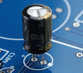
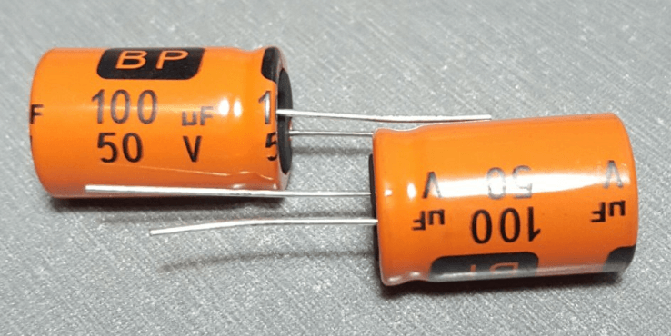
2.2 Electrolytic Capacitors
- Aluminum Electrolytic Capacitors:
- High capacitance (µF to mF range).
- Polarized (must be connected with correct polarity).
- Used in power supply filtering due to high energy storage.
- Suffer from high ESR and limited lifespan (drying out of electrolyte).
- Tantalum Capacitors:
- Smaller size than aluminum electrolytics.
- Lower leakage current and better stability.
- More expensive and sensitive to voltage spikes.
- Applications:
- Power supply decoupling.
- Energy storage in DC-DC converters.
- Audio and low-frequency filtering.
2.3 Film Capacitors
- Materials: Polyester (Mylar), Polypropylene (PP), Polycarbonate.
- Advantages:
- High stability and reliability.
- Low dielectric absorption.
- Non-polarized and suitable for AC applications.
- Disadvantages:
- Larger physical size compared to ceramics.
- Limited high-frequency performance.
- Applications:
- Timing circuits (RC networks).
- EMI suppression.
- Motor run and snubber circuits.
2.4 Supercapacitors (Ultracapacitors)
- Features:
- Extremely high capacitance (Farad range).
- Used for energy storage instead of batteries.
- Fast charge/discharge cycles.
- Applications:
- Backup power for memory circuits.
- Energy harvesting systems.
- High-power pulse applications.
3. Key Parameters in Capacitor Selection
When selecting a capacitor for a PCB, several critical parameters must be considered:
3.1 Capacitance Value (C)
- Determines the energy storage capability.
- Must match the circuit requirements (e.g., decoupling, filtering).
3.2 Voltage Rating
- The maximum voltage a capacitor can handle without breakdown.
- Should exceed the circuit’s operating voltage by at least 20-50%.
3.3 Equivalent Series Resistance (ESR)
- Resistance in the capacitor leads and plates, causing power loss.
- Critical in high-frequency and power applications (low ESR preferred).
3.4 Temperature Coefficient
- How capacitance changes with temperature.
- Important for stable performance in extreme environments.
3.5 Dielectric Material
- Affects capacitance stability, leakage, and frequency response.
- Example: NP0/C0G for stable RF circuits, X7R for general-purpose use.
3.6 Size and Footprint
4. Applications of PCB Capacitors
4.1 Decoupling and Bypassing
- Used near IC power pins to suppress noise and stabilize voltage.
- Ceramic capacitors (0.1µF – 10µF) are commonly used.
4.2 Filtering
- Low-pass filters remove high-frequency noise.
- Electrolytic and ceramic capacitors are combined for wideband filtering.
4.3 Timing Circuits
- RC networks use film or ceramic capacitors for precise timing.
4.4 Energy Storage
- Supercapacitors provide short-term power backup.
- Electrolytics store energy in power supplies.
4.5 Coupling and DC Blocking
- Film capacitors block DC while allowing AC signals to pass.
5. PCB Layout Considerations for Capacitors
Proper placement and routing are essential for optimal capacitor performance:
- Place decoupling capacitors close to IC power pins.
- Minimize trace length to reduce parasitic inductance.
- Use multiple capacitors in parallel for wide-frequency decoupling.
- Avoid placing noisy traces near sensitive capacitor nodes.
6. Conclusion
PCB capacitors are vital components in electronic design, each type offering unique advantages for specific applications. Engineers must carefully consider capacitance value, voltage rating, ESR, and temperature stability when selecting capacitors. Proper PCB layout ensures optimal performance, reducing noise and improving circuit reliability. As technology advances, new capacitor materials and miniaturized designs continue to enhance electronic systems.
By understanding the characteristics and applications of different capacitor types, designers can make informed decisions to improve circuit efficiency and longevity.