FR4 PCB: The Backbone of Modern Electronics
Introduction
Printed Circuit Boards (PCBs) are the foundation of nearly all modern electronic devices. Among the various types of PCB materials, FR4 is the most widely used due to its excellent electrical insulation, mechanical strength, and thermal stability. This article explores FR4 PCB in detail, covering its composition, properties, advantages, applications, manufacturing process, and comparisons with alternative materials.
1. What is FR4 PCB?
FR4 stands for Flame Retardant 4, a grade designation for a glass-reinforced epoxy laminate material. It is a composite made of woven fiberglass cloth with an epoxy resin binder, making it flame-resistant and highly durable. FR4 is the standard substrate material for rigid PCBs, offering a balance of performance, cost-effectiveness, and manufacturability.
Key Components of FR4:
- Fiberglass Weave: Provides mechanical strength and rigidity.
- Epoxy Resin: Binds the fiberglass and provides insulation.
- Flame Retardant Additives: Ensure compliance with safety standards (UL94-V0).
2. Properties of FR4 PCB
FR4 PCBs exhibit several key properties that make them ideal for a wide range of applications:
A. Electrical Properties
- High Dielectric Strength: Resists electrical breakdown under high voltage.
- Low Electrical Conductivity: Excellent insulator, preventing short circuits.
- Stable Dielectric Constant (Dk): Typically around 4.3–4.8 at 1 MHz, ensuring consistent signal integrity.
B. Mechanical Properties
- High Tensile Strength: Resists bending and breaking.
- Dimensional Stability: Minimal expansion or contraction under temperature changes.
- Good Flexural Strength: Supports heavy components without warping.
C. Thermal Properties
- Glass Transition Temperature (Tg): Standard FR4 has a Tg of ~130°C; high-Tg FR4 (Tg > 170°C) is available for high-temperature applications.
- Thermal Conductivity: Low (~0.3 W/m·K), meaning it does not dissipate heat well (may require heat sinks or thermal vias).
D. Chemical & Environmental Resistance
- Moisture Resistant: Low water absorption (~0.1%).
- Flame Retardant: Meets UL94-V0 standards.
- Resistant to Chemicals: Withstands most solvents and acids used in PCB manufacturing.
3. Advantages of FR4 PCB
FR4 is the most popular PCB substrate due to the following benefits:
- Cost-Effective: Cheaper than high-frequency or metal-core PCBs.
- Widely Available: Easy to source from multiple suppliers.
- Ease of Manufacturing: Compatible with standard PCB fabrication processes.
- Good Performance: Balances electrical, mechanical, and thermal properties.
- Versatility: Suitable for a broad range of applications, from consumer electronics to industrial systems.
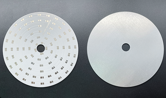
4. Applications of FR4 PCB
FR4 PCBs are used in nearly every industry, including:
- Consumer Electronics: Smartphones, laptops, TVs, and home appliances.
- Automotive Electronics: Engine control units (ECUs), infotainment systems.
- Industrial Equipment: Control systems, power supplies, and automation devices.
- Medical Devices: Diagnostic equipment, patient monitoring systems.
- Telecommunications: Routers, switches, and base stations.
- Aerospace & Defense: Avionics, radar systems, and military hardware.
5. FR4 PCB Manufacturing Process
The production of FR4 PCBs involves several key steps:
Step 1: Design & Layout
- PCB schematics are designed using CAD software (e.g., Altium, KiCad).
- Copper traces, vias, and component placements are defined.
Step 2: Material Preparation
- FR4 sheets are coated with copper foil (1 oz, 2 oz, etc.).
- A photosensitive resist is applied for patterning.
Step 3: Etching
- Unwanted copper is chemically etched away, leaving conductive traces.
Step 4: Lamination (for Multilayer PCBs)
- Multiple FR4 layers are bonded under heat and pressure.
Step 5: Drilling & Plating
- Holes for vias and component leads are drilled.
- Plating (electroless or electrolytic) ensures conductivity.
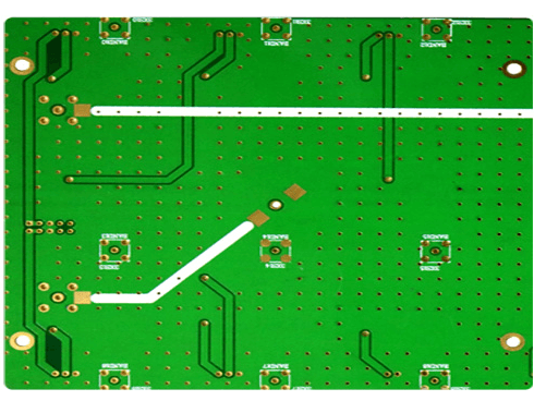
Step 6: Solder Mask & Silkscreen Application
- A protective solder mask (usually green) is applied.
- Silkscreen labels (component markings) are printed.
Step 7: Surface Finish
- Coatings like HASL, ENIG, or OSP are applied to prevent oxidation.
Step 8: Testing & Inspection
- Electrical testing (continuity, impedance).
- Automated Optical Inspection (AOI) for defects.
6. FR4 vs. Alternative PCB Materials
While FR4 is the industry standard, some applications require alternative materials:
| Property | FR4 | Rogers (High-Frequency) | Polyimide (Flex PCBs) | Metal-Core (MCPCB) |
|---|---|---|---|---|
| Dielectric Constant (Dk) | 4.3–4.8 | 2.2–10.2 | 3.5–4.0 | 3.0–5.0 |
| Thermal Conductivity | Low (~0.3 W/m·K) | Medium (~0.6 W/m·K) | Low (~0.2 W/m·K) | High (1–4 W/m·K) |
| Max Operating Temp | ~130°C (standard) | ~280°C | ~260°C | ~150°C |
| Cost | Low | High | Medium | Medium-High |
| Applications | General-purpose PCBs | RF/microwave circuits | Flexible electronics | LED lighting, power electronics |
When to Choose FR4?
- For cost-sensitive, general-purpose PCBs.
- When high-frequency performance is not critical.
- For rigid boards with moderate thermal requirements.
When to Avoid FR4?
- For high-frequency RF designs (use Rogers or PTFE).
- For flexible circuits (use polyimide).
- For high-power LED or power electronics (use MCPCB).
7. Challenges & Limitations of FR4
Despite its advantages, FR4 has some limitations:
- Poor High-Frequency Performance: Higher dielectric loss than specialized RF materials.
- Limited Thermal Conductivity: Requires additional cooling solutions for high-power applications.
- Lower Tg in Standard Grades: May warp under extreme heat unless high-Tg FR4 is used.
8. Future Trends in FR4 PCB Technology
- High-Tg & Low-Loss FR4: Improved versions for 5G and high-speed applications.
- Halogen-Free FR4: Eco-friendly alternatives for RoHS compliance.
- Hybrid PCBs: Combining FR4 with high-frequency materials for mixed-signal designs.
- Advanced Manufacturing: Laser drilling and additive techniques for finer traces.
Conclusion
FR4 PCB remains the dominant choice in electronics due to its excellent balance of cost, performance, and manufacturability. While it may not be suitable for ultra-high-frequency or extreme thermal applications, its versatility ensures it will continue to be the backbone of PCB technology for years to come. As electronics evolve, advancements in FR4 materials will further expand its capabilities, maintaining its relevance in an ever-changing industry.
This article provides a comprehensive overview of FR4 PCBs, covering their properties, benefits, manufacturing, and applications. Would you like any additional details on specific aspects, such as high-frequency FR4 variants or design best practices?