Thermocouple Connectors PCB: Design, Applications, and Best Practices
Introduction
Thermocouple connectors play a critical role in temperature measurement systems, serving as the interface between thermocouple wires and measurement instrumentation. When integrated with printed circuit boards (PCBs), these connectors enable reliable, accurate temperature monitoring in various industrial, scientific, and commercial applications. This 2000-word article explores thermocouple connectors for PCBs, covering their fundamentals, design considerations, material selection, installation practices, and common applications.
Fundamentals of Thermocouple Connectors
What Are Thermocouple Connectors?
Thermocouple connectors are specialized electrical components designed to maintain the integrity of thermoelectric voltage signals generated by thermocouples. Unlike standard electrical connectors, they must preserve the specific metal-to-metal junctions that create the Seebeck effect—the principle behind thermocouple operation.
When mounted on PCBs, these connectors provide:
- Secure mechanical attachment for thermocouple wires
- Proper electrical contact maintaining thermoelectric properties
- Environmental protection for sensitive junctions
- Easy connection/disconnection for maintenance or replacement
Thermoelectric Considerations
The unique requirement for thermocouple connectors stems from the physics of thermocouples. A thermocouple generates a small voltage proportional to temperature differences between its measurement junction (hot end) and reference junction (cold end). Any additional junctions introduced in the circuit—including those at connectors—must be carefully managed to avoid measurement errors.
PCB-mounted thermocouple connectors must maintain:
- Material matching: Connector contacts must match the thermocouple alloy types (K, J, T, E, etc.)
- Isothermal blocks: The entire connector should maintain uniform temperature to prevent parasitic junctions
- Polarity preservation: Correct orientation of positive and negative thermocouple wires
Types of PCB Thermocouple Connectors
1. Pluggable Terminal Blocks
Features:
- Screw or spring clamp termination
- Color-coded by thermocouple type
- Typically 2-pin configuration
- Common pitch sizes: 3.81mm, 5.08mm, 7.62mm
Advantages:
- Field-replaceable without soldering
- Accommodates various wire gauges
- High vibration resistance
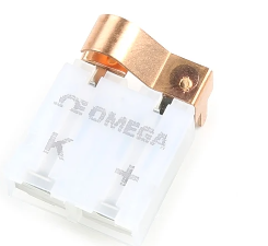
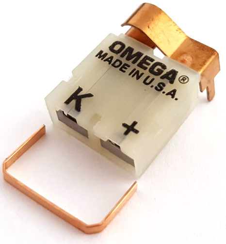
2. Miniature Thermocouple Sockets
Features:
- Compact footprint for space-constrained designs
- Often used with pluggable thermocouple probes
- Available in surface-mount (SMD) and through-hole versions
Advantages:
- Low-profile installation
- Suitable for automated assembly
- Cost-effective for high-volume production
3. Board-to-Wire Connectors
Features:
- Direct wire-to-PCB connection
- Includes insulation displacement or crimp contacts
- May include strain relief features
Advantages:
- Permanent, reliable connections
- Eliminates intermediate termination points
- Minimizes potential error sources
4. High-Density Array Connectors
Features:
- Multiple thermocouple channels in single housing
- Common in data acquisition systems
- Often includes shielding provisions
Advantages:
- Space efficiency for multi-channel systems
- Consistent connector performance across channels
- Integrated ESD protection options
PCB Design Considerations
Material Selection
Connector Housing:
- High-temperature thermoplastics (PPS, PEEK, LCP)
- UL94 V-0 flame rating for industrial applications
- Chemical resistance matching operational environment
Contact Materials:
Must exactly match thermocouple type:
- Type K: Chromel/Alumel
- Type J: Iron/Constantan
- Type T: Copper/Constantan
- Type E: Chromel/Constantan
PCB Materials:
- FR-4 standard for moderate temperatures
- Polyimide or ceramic substrates for high-temp applications
- Thick copper (2oz+) for current-carrying capacity
Layout Guidelines
- Isothermal Design:
- Group all reference junctions together
- Use thermal relief pads to minimize heat transfer
- Consider copper pours as thermal equalizers
- Signal Integrity:
- Keep thermocouple traces short and direct
- Maintain adequate spacing from power traces
- Use guard rings around sensitive inputs
- Mechanical Considerations:
- Reinforced mounting for connectors experiencing strain
- Adequate clearance for wire bending radius
- Strain relief features for cable exits
Grounding and Shielding
Proper grounding is essential for noise immunity:
- Use single-point grounding for thermocouple circuits
- Separate analog and digital grounds
- Implement shielded connectors for noisy environments
- Consider Faraday cages for extreme EMI protection
Installation and Maintenance Best Practices
Soldering Techniques
For through-hole connectors:
- Use temperature-controlled soldering irons (300-350°C)
- Apply solder to the pad, not the iron tip
- Limit contact time to prevent thermal damage
- Use no-clean flux to avoid contamination
For surface-mount connectors:
- Follow manufacturer’s reflow profile exactly
- Ensure proper pad geometry for reliable joints
- Consider post-assembly inspection (X-ray for BGA styles)
Connection Procedures
- Verify thermocouple type matches connector
- Observe proper polarity (positive/negative terminals)
- Strip only enough insulation to make contact
- Secure wires firmly without over-tightening
- Apply appropriate strain relief
Maintenance Considerations
- Periodic inspection for:
- Contact oxidation
- Mechanical looseness
- Insulation damage
- Cleaning procedures:
- Use isopropyl alcohol for contact cleaning
- Avoid abrasive materials that could damage plating
- Replacement indicators:
- Increased measurement noise
- Intermittent connections
- Physical damage to housing
Applications of PCB Thermocouple Connectors
Industrial Process Control
- Plastic injection molding machines
- Extrusion process monitoring
- Heat treatment furnaces
- Semiconductor manufacturing
Energy Systems
- Power plant temperature monitoring
- Solar thermal collector arrays
- Geothermal system controls
- Battery temperature management
Scientific and Laboratory
- Material research chambers
- Cryogenic systems
- Environmental test equipment
- Calibration instrumentation
Automotive and Aerospace
- Engine performance monitoring
- Exhaust gas temperature measurement
- Brake temperature sensing
- Avionics thermal management
Medical Equipment
- Sterilization systems
- Laboratory analyzers
- Therapeutic heating devices
- Medical device manufacturing
Emerging Trends and Future Developments
Miniaturization
- Nano-D connectors for space-constrained applications
- Micro-thermocouple interfaces for MEMS devices
- Flexible PCB integration for wearable sensors
Smart Connectors
- Embedded temperature sensors for cold junction compensation
- RFID tagging for maintenance tracking
- Connector-integrated signal conditioning
Advanced Materials
- Graphene-based contacts for improved stability
- High-temperature superconducting interfaces
- Self-cleaning contact coatings
Industry 4.0 Integration
- IIoT-enabled connectors with digital interfaces
- Predictive maintenance capabilities
- Cloud-based calibration tracking
Conclusion
PCB-mounted thermocouple connectors represent a critical intersection of thermal measurement science and electronic packaging technology. Proper selection, design, and implementation of these components ensures accurate temperature monitoring across countless industrial and scientific applications. By understanding the unique requirements of thermocouple circuits—particularly the need for material matching and isothermal design—engineers can develop reliable temperature measurement systems that maintain signal integrity from sensor to processing electronics.
As temperature monitoring becomes increasingly important in energy efficiency, process optimization, and safety systems, the evolution of thermocouple connector technology will continue to play a vital role in measurement accuracy and system reliability. Future developments in miniaturization, smart interfaces, and advanced materials promise to further enhance the performance and capabilities of these essential components.