CAF Effect Leading to PCB Leakage: Causes, Mechanisms, and Mitigation Strategies
Abstract
Conductive Anodic Filament (CAF) formation is a critical reliability issue in printed circuit boards (PCBs), leading to insulation resistance degradation and electrical leakage between conductors. This phenomenon occurs due to electrochemical migration under humid and biased conditions, resulting in dendritic growth between anode and cathode. This paper explores the root causes of CAF, its impact on PCB performance, detection methods, and mitigation strategies to enhance long-term reliability in electronic assemblies.
Keywords: CAF (Conductive Anodic Filament), PCB reliability, electrochemical migration, insulation resistance, dendritic growth
1. Introduction
Printed Circuit Boards (PCBs) are fundamental components in modern electronics, providing mechanical support and electrical connections. However, environmental stresses such as humidity, temperature fluctuations, and electrical bias can lead to failure mechanisms like Conductive Anodic Filament (CAF) formation. CAF is an electrochemical process that creates conductive pathways between adjacent conductors, causing leakage currents, short circuits, and eventual system failure.
As electronic devices shrink in size, the spacing between PCB traces decreases, increasing susceptibility to CAF. This paper examines the CAF mechanism, influencing factors, detection techniques, and preventive measures to improve PCB reliability.
2. Mechanism of CAF Formation
CAF occurs due to electrochemical reactions in the presence of moisture, ionic contaminants, and an applied voltage. The process involves several stages:
2.1 Electrochemical Migration
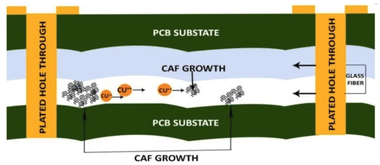
Under humid conditions, water absorption in the PCB substrate (e.g., FR-4) dissolves ionic residues (e.g., halides, sulfates). When a voltage is applied, electrochemical reactions initiate at the anode (positive electrode), leading to metal dissolution (typically copper).
2.2 Ion Transport and Dendritic Growth
Dissolved metal ions (Cu²⁺) migrate toward the cathode (negative electrode) through microcracks or glass-resin interfaces in the PCB. At the cathode, ions reduce back to metal, forming dendritic filaments that grow over time.
2.3 Formation of Conductive Path
As the dendrites bridge the anode and cathode, a low-resistance path forms, causing leakage currents and eventual short circuits.
3. Factors Influencing CAF Formation
Several factors contribute to CAF susceptibility:
3.1 Material Properties
- Substrate Composition: FR-4 epoxy resins with poor moisture resistance are more prone to CAF.
- Glass Transition Temperature (Tg): Higher Tg materials exhibit better resistance to moisture absorption.
- Filler Materials: Halogen-free laminates reduce ionic contamination.
3.2 Environmental Conditions
- Humidity: High humidity (>85% RH) accelerates ion migration.
- Temperature: Elevated temperatures (>85°C) enhance electrochemical reactions.
- Voltage Bias: Higher voltages increase ion mobility.
3.3 PCB Design and Manufacturing
- Trace Spacing: Narrow conductor gaps (<0.2 mm) increase CAF risk.
- Plating Quality: Poor copper plating or voids promote ion migration.
- Surface Contamination: Residual flux or cleaning agents introduce ionic species.
4. Detection and Failure Analysis of CAF
Early detection of CAF is crucial to prevent catastrophic failures. Common diagnostic methods include:
4.1 Electrical Testing
- Insulation Resistance (IR) Measurement: A drop in IR indicates leakage paths.
- Time-Domain Reflectometry (TDR): Locates CAF-induced impedance changes.
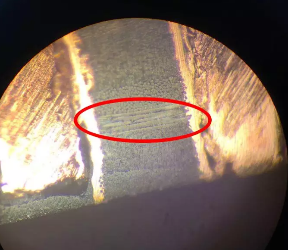
4.2 Microscopic Inspection
- Optical Microscopy: Identifies dendritic growth between conductors.
- Scanning Electron Microscopy (SEM): Reveals filament structure at high resolution.
4.3 Accelerated Aging Tests
- Temperature-Humidity-Bias (THB) Testing: Simulates harsh conditions to induce CAF.
- IPC-TM-650 Test Methods: Standardized procedures for CAF evaluation.
5. Mitigation Strategies for CAF Prevention
To enhance PCB reliability, manufacturers adopt several countermeasures:
5.1 Material Selection
- High-Tg and Low-Dk/Df Substrates: Improve moisture resistance.
- CAF-Resistant Laminates: Use reinforced epoxy or polyimide materials.
5.2 Improved PCB Design
- Increased Conductor Spacing: Maintain >0.3 mm gaps in high-humidity applications.
- Guard Traces: Isolate high-voltage traces to prevent ion migration.
5.3 Manufacturing Process Control
- Optimized Cleaning Processes: Remove ionic contaminants post-assembly.
- Conformal Coatings: Apply moisture-blocking layers (e.g., acrylic, silicone).
5.4 Environmental Protection
- Hermetic Sealing: Prevents moisture ingress in critical applications.
- Desiccants: Absorb residual humidity in enclosed systems.
6. Case Study: CAF-Induced Failure in Automotive Electronics
A study on automotive control modules revealed CAF-related failures after prolonged exposure to high humidity. Analysis showed dendritic growth between 12V power and ground traces, leading to intermittent shorts. Implementing CAF-resistant materials and conformal coatings reduced failure rates by 80%.
7. Conclusion
CAF formation remains a significant reliability challenge in PCBs, particularly in miniaturized and high-density designs. Understanding the electrochemical mechanisms, environmental influences, and detection methods is essential for preventing leakage and short circuits. By adopting CAF-resistant materials, optimized designs, and stringent manufacturing controls, PCB reliability can be significantly improved.
Future research should focus on advanced materials (e.g., nanocomposites) and real-time CAF monitoring techniques to further mitigate this failure mode.