Analysis of the Design and Retrofit of PCB Incinerators
Abstract
Printed Circuit Board (PCB) incineration is a critical process in electronic waste management, aimed at recovering valuable metals and reducing environmental pollution. However, the design and operation of PCB incinerators must address challenges such as toxic emissions, energy efficiency, and regulatory compliance. This paper explores the fundamental design principles of PCB incinerators, analyzes common operational issues, and discusses retrofit strategies to enhance performance. Key considerations include combustion optimization, emission control systems, and waste heat recovery. Case studies of successful retrofits are presented to illustrate practical improvements in efficiency and environmental safety.
Keywords: PCB incineration, waste management, emission control, thermal efficiency, incinerator retrofit
1. Introduction
The rapid growth of electronic waste (e-waste) has necessitated the development of efficient disposal methods, particularly for PCBs, which contain hazardous materials like heavy metals and brominated flame retardants. Incineration is a widely used method for PCB treatment, as it reduces waste volume and enables metal recovery. However, improper incinerator design can lead to the release of toxic pollutants such as dioxins, furans, and particulate matter.
This paper examines the design and retrofit of PCB incinerators, focusing on combustion technology, emission control, and energy recovery. By analyzing existing systems and retrofit solutions, we aim to provide insights into optimizing incinerator performance while minimizing environmental impact.
2. Design Principles of PCB Incinerators
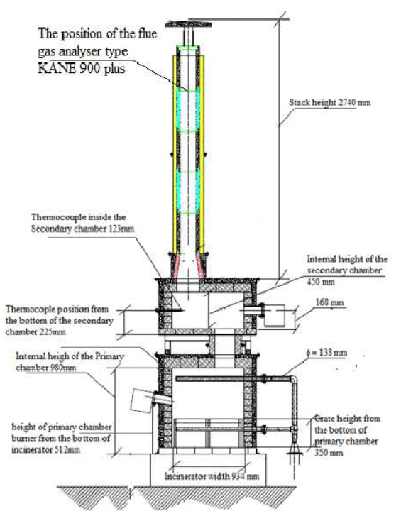
2.1 Combustion Chamber Design
The combustion chamber is the core component of a PCB incinerator, where high-temperature oxidation breaks down organic materials. Key design parameters include:
- Temperature Control: Maintaining temperatures between 850°C and 1200°C ensures complete combustion of organic compounds while preventing the formation of dioxins.
- Residence Time: A minimum of 2 seconds is required to ensure complete decomposition of toxic substances.
- Turbulence and Mixing: Proper air-fuel mixing enhances combustion efficiency and reduces unburned residues.
2.2 Secondary Combustion Systems
Many modern incinerators incorporate a secondary combustion chamber to further oxidize any remaining volatile organic compounds (VOCs) and carbon monoxide (CO). This stage operates at higher temperatures (1000°C–1200°C) with additional air injection.
2.3 Emission Control Systems
To mitigate harmful emissions, PCB incinerators integrate several pollution control technologies:
- Scrubbers: Wet scrubbers remove acidic gases (HCl, SO₂) through chemical neutralization.
- Baghouse Filters: These capture particulate matter and heavy metals.
- Activated Carbon Injection: Used to adsorb dioxins and furans before gas discharge.
- Selective Catalytic Reduction (SCR): Reduces nitrogen oxides (NOₓ) through catalytic reactions.
2.4 Heat Recovery Systems
Waste heat recovery improves energy efficiency by converting excess heat into steam or electricity. Common methods include:
- Boilers and Heat Exchangers: Extract thermal energy from flue gases.
- Cogeneration Systems: Utilize recovered heat for power generation or industrial processes.
3. Common Challenges in PCB Incineration
3.1 Toxic Emissions
Incomplete combustion can release hazardous substances, including:
- Dioxins and Furans: Formed at temperatures between 250°C and 450°C if combustion is inadequate.
- Heavy Metals: Lead, cadmium, and mercury may volatilize and require advanced filtration.
3.2 Corrosion and Wear
The high chlorine content in PCBs accelerates corrosion in incinerator components, necessitating the use of corrosion-resistant materials like refractory linings and nickel alloys.
3.3 Regulatory Compliance
Strict environmental regulations (e.g., EU WEEE Directive, U.S. EPA standards) mandate low emission levels, requiring continuous monitoring and system upgrades.
4. Retrofitting PCB Incinerators for Enhanced Performance
4.1 Combustion Optimization
- Oxygen Enrichment: Increases combustion efficiency and reduces unburned residues.
- Advanced Burner Systems: Improve temperature uniformity and reduce NOₓ formation.
4.2 Advanced Emission Control Upgrades
- Electrostatic Precipitators (ESPs): Enhance particulate removal efficiency.
- Catalytic Filters: Combine particulate filtration with dioxin decomposition.
4.3 Energy Efficiency Improvements
- Waste Heat Recovery Integration: Adding ORC (Organic Rankine Cycle) systems to convert low-grade heat into electricity.
- Automated Control Systems: AI-based monitoring optimizes combustion in real-time.
4.4 Case Study: Retrofit of a European PCB Incinerator
A facility in Germany implemented SCR and waste heat recovery, achieving:
- 40% reduction in NOₓ emissions
- 15% improvement in energy efficiency
- Compliance with EU emission standards
5. Future Trends in PCB Incineration Technology
- Plasma Arc Gasification: Offers higher temperatures and lower emissions.
- AI-Driven Process Control: Enhances operational efficiency and predictive maintenance.
- Circular Economy Integration: Metal recovery and reuse of incineration byproducts.
6. Conclusion
The design and retrofit of PCB incinerators play a crucial role in sustainable e-waste management. By optimizing combustion, enhancing emission controls, and improving energy recovery, modern incinerators can achieve high efficiency while meeting environmental regulations. Future advancements in plasma technology and AI will further revolutionize PCB waste treatment.