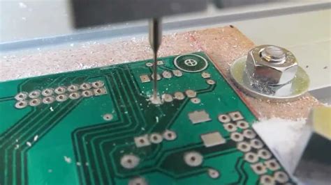
Key Characteristics of High-Reliability PCBs
Introduction
Printed Circuit Boards (PCBs) are the backbone of modern electronics, serving as the foundation for nearly all electronic devices. While standard PCBs are sufficient for everyday consumer electronics, high-reliability PCBs are essential for industries where failure is not an option—such as aerospace, defense, medical, automotive, and industrial applications.
High-reliability PCBs are designed to withstand harsh environments, prolonged operational life, and extreme conditions without degradation in performance. This article explores the critical characteristics that define high-reliability PCBs, including material selection, design considerations, manufacturing processes, and testing protocols.
1. High-Quality Base Materials
The foundation of a high-reliability PCB lies in its base materials. Standard PCBs typically use FR-4, a flame-retardant fiberglass epoxy laminate. However, high-reliability applications demand superior materials with enhanced thermal, mechanical, and electrical properties.
Key Material Considerations:
- High-Tg (Glass Transition Temperature) Materials:
- Standard FR-4 has a Tg of around 130–140°C, whereas high-reliability PCBs use materials with Tg ≥ 170°C to withstand high-temperature operations.
- Examples: Polyimide, Rogers laminates, and Teflon-based substrates.
- Low CTE (Coefficient of Thermal Expansion):
- Materials with a low CTE reduce stress on solder joints during thermal cycling, preventing cracks and delamination.
- Ceramic-filled PTFE and specialized epoxy resins are common choices.
- Low Dielectric Loss and High Frequency Stability:
- Critical for RF and high-speed digital applications where signal integrity is paramount.

2. Robust PCB Design Considerations
A well-designed PCB is crucial for reliability. High-reliability PCBs incorporate several design enhancements to minimize failure risks.
Critical Design Features:
- Controlled Impedance Traces:
- Ensures signal integrity in high-speed and RF circuits by maintaining consistent impedance.
- Requires precise trace width, spacing, and dielectric thickness calculations.
- Thermal Management:
- Incorporation of thermal vias, heatsinks, and copper pours to dissipate heat efficiently.
- Use of thick copper layers (2 oz or more) for high-current applications.
- Redundancy and Fault Tolerance:
- Critical circuits may include redundant traces or fail-safe mechanisms.
- Isolated power planes to prevent cascading failures.
- EMI/EMC Shielding:
- Proper grounding strategies, shielding layers, and differential signaling to minimize electromagnetic interference.
3. Advanced Manufacturing Processes
High-reliability PCBs require stringent manufacturing controls to ensure consistency and defect-free production.
Key Manufacturing Techniques:
- Laser Direct Imaging (LDI):
- Provides higher precision than traditional photolithography, reducing alignment errors.
- Sequential Lamination:
- Used in multilayer PCBs to ensure proper layer alignment and prevent delamination.
- Plated Through-Holes (PTH) with Microvias:
- Ensures strong electrical connections in high-density interconnects (HDI) PCBs.
- Microvias improve signal integrity in high-frequency designs.
- Surface Finishes for Enhanced Durability:
- ENIG (Electroless Nickel Immersion Gold) – Excellent corrosion resistance.
- Immersion Silver or Hard Gold – Used in high-wear applications like connectors.

4. Strict Quality Control and Testing
High-reliability PCBs undergo rigorous testing to detect potential failures before deployment.
Essential Testing Methods:
- Automated Optical Inspection (AOI):
- Detects soldering defects, misalignments, and missing components.
- X-Ray Inspection:
- Examines internal layers, vias, and BGA solder joints for hidden defects.
- Environmental Stress Testing:
- Thermal Cycling: Exposes PCBs to extreme temperature fluctuations to test durability.
- Vibration and Shock Testing: Ensures resilience in automotive and aerospace applications.
- Electrical Testing:
- Continuity Testing: Verifies proper electrical connections.
- High-Potential (Hi-Pot) Testing: Checks insulation integrity under high voltage.
5. Compliance with Industry Standards
High-reliability PCBs must adhere to stringent industry standards, including:
- IPC-6012: Qualification and performance specifications for rigid PCBs.
- IPC-A-600: Acceptability criteria for PCB manufacturing.
- MIL-PRF-31032: Military-grade PCB requirements.
- ISO 9001 & AS9100: Quality management for aerospace applications.
Conclusion
High-reliability PCBs are indispensable in mission-critical applications where failure can lead to catastrophic consequences. Their superior material selection, robust design, advanced manufacturing techniques, and rigorous testing ensure long-term performance under extreme conditions.
By adhering to industry standards and continuously improving fabrication processes, manufacturers can produce PCBs that meet the highest reliability demands. As technology evolves, the development of even more resilient PCBs will be crucial for next-generation electronics in aerospace, medical, and industrial automation.
Investing in high-reliability PCBs not only enhances product longevity but also reduces costly downtime and maintenance, making them a cornerstone of modern high-performance electronics.


