The Purpose and Importance of PCB Thickness Stackup in Modern Electronics
Introduction
Printed Circuit Board (PCB) thickness stackup refers to the arrangement of copper layers and insulating materials that make up the structure of a PCB. This deliberate organization of conductive and dielectric layers serves multiple critical functions in electronic design and manufacturing. As electronic devices become increasingly complex while shrinking in size, proper PCB stackup has emerged as one of the most crucial considerations in board design. This article explores the various reasons why engineers carefully plan and implement specific PCB thickness stackups, examining the electrical, mechanical, thermal, and manufacturing considerations that drive these decisions.
Electrical Performance Considerations
Signal Integrity Maintenance
One of the primary reasons for careful PCB stackup design is to maintain optimal signal integrity, especially in high-speed digital circuits and high-frequency analog applications. The thickness and arrangement of layers directly affect:
- Impedance control: Precise thickness management allows designers to achieve specific characteristic impedances (typically 50Ω or 100Ω differential) necessary for proper signal transmission. The dielectric thickness between a signal layer and its reference plane largely determines the trace impedance.
- Crosstalk reduction: Proper stackup provides adequate separation between signal layers and arranges adjacent signal layers perpendicular to each other to minimize electromagnetic interference between traces.
- Return path management: A well-designed stackup ensures every signal layer has an adjacent reference plane (power or ground) to provide low-impedance return paths for high-frequency signals.
Power Integrity Optimization
PCB stackup significantly impacts power distribution network (PDN) performance:
- Decoupling effectiveness: Thin dielectrics between power and ground planes create natural planar capacitance that helps stabilize power supply voltages.
- Power plane segmentation: Strategic layer arrangement allows for multiple voltage domains while minimizing noise coupling between them.
- IR drop reduction: Appropriate copper weights (thicknesses) in power planes decrease resistance in power distribution networks.
Mechanical and Structural Considerations
Board Rigidity and Durability
The total PCB thickness and layer composition directly affect the board’s mechanical properties:
- Flexural strength: Thicker boards with proper layer symmetry resist bending and warpage, crucial for large boards or those used in mechanically stressful environments.
- Vibration resistance: Certain stackups better withstand mechanical vibration, important for automotive, aerospace, and industrial applications.
- Connector reliability: The board thickness must match the expected mechanical stress at connection points, especially for edge connectors or heavy components.
Layer Symmetry and Warpage Prevention
A balanced stackup prevents manufacturing defects and long-term reliability issues:
- Copper distribution: Symmetrical copper layer distribution across the board’s central plane prevents uneven thermal expansion that causes warping.
- Material selection: Alternating high and low dielectric constant materials can help balance stresses.
- Thermal expansion matching: Layer materials and thicknesses are chosen to minimize coefficient of thermal expansion (CTE) mismatches.
Thermal Management
Heat Dissipation
PCB stackup plays a significant role in thermal performance:
- Thermal vias and planes: Thicker copper layers (2oz or more) in power planes help spread heat away from concentrated heat sources.
- Dielectric material selection: High thermal conductivity prepreg materials enhance vertical heat transfer through the board.
- Layer arrangement: Positioning high-power components near thermal dissipation layers improves cooling efficiency.
Thermal Stress Reduction
Proper stackup design minimizes thermal-related reliability issues:
- CTE matching: Layer materials are selected to have compatible thermal expansion characteristics.
- Heat spreading: Strategic placement of copper layers prevents localized hot spots that could lead to material degradation.
Manufacturing and Assembly Factors
Fabrication Yield Improvement
Thoughtful stackup design enhances manufacturability:
- Layer count optimization: Choosing standard layer counts and thicknesses reduces cost and improves yield.
- Material availability: Stackups using standard core/prepreg thicknesses avoid special orders and delays.
- Registration tolerance: Appropriate thickness choices account for layer-to-layer alignment tolerances in multilayer boards.
Assembly Process Compatibility
PCB thickness affects component assembly:
- Wave soldering: Thicker boards require different thermal profiles during soldering.
- Component compatibility: Very thin boards may require stiffeners for certain assembly processes.
- Via filling: Stackup design influences the feasibility of via filling processes like via-in-pad.
Special Application Requirements
High-Speed Design
Advanced applications demand specific stackup characteristics:
- Low-loss materials: High-frequency designs often require specialized dielectric materials with tight thickness tolerances.
- Stripline configurations: Sensitive RF signals may require symmetrical stripline arrangements with precise dielectric spacing.
- Mixed-signal isolation: Careful layer stacking separates analog and digital sections to prevent noise coupling.
HDI (High Density Interconnect) Boards
Ultra-compact designs utilize sophisticated stackups:
- Microvia integration: Stackups accommodate laser-drilled microvias for dense interconnections.
- Thin dielectrics: Very thin insulating layers enable fine-pitch component mounting.
- Sequential lamination: Complex HDI boards may require multiple lamination steps with different layer thicknesses.
Cost Optimization
Material Efficiency
Strategic stackup design reduces unnecessary expense:
- Layer count minimization: Using the fewest layers possible for the application reduces cost.
- Copper weight selection: Choosing appropriate copper thicknesses avoids material waste.
- Standard materials: Stackups based on commonly available materials are more economical.
Yield and Reliability
Proper stackups indirectly reduce costs by:
- Reducing scrap: Good stackup design minimizes manufacturing defects.
- Improving reliability: Well-designed boards have fewer field failures and returns.
- Simplifying testing: Logical layer arrangements make boards easier to test and debug.
Future Trends in PCB Stackup Design
As technology advances, PCB stackup considerations continue to evolve:
- Embedded components: Layers may incorporate passive components or even active dies within the board structure.
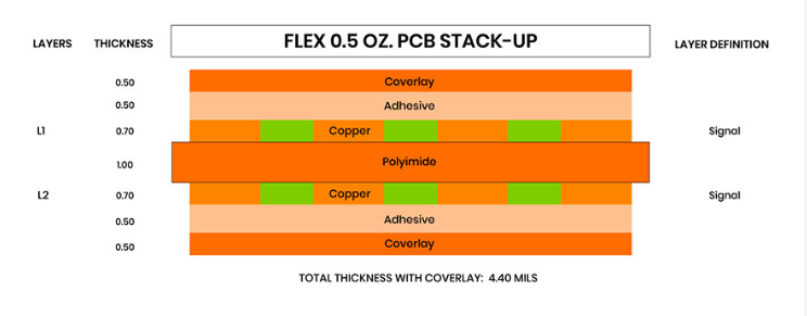
- Flex-rigid integration: Stackups combine rigid and flexible sections in single designs.
- Advanced materials: New dielectric materials with better electrical and thermal properties enable novel stackup approaches.
- 3D packaging: Stackups increasingly interact with package-level and system-level 3D integration schemes.
Conclusion
PCB thickness stackup serves as a foundational element in electronic design, affecting nearly every aspect of board performance, reliability, and manufacturability. Far from being an arbitrary construction detail, the careful planning of layer thicknesses and materials represents a critical engineering compromise between electrical requirements, mechanical demands, thermal considerations, and economic factors. As electronic systems grow more sophisticated while physical dimensions shrink, the importance of proper PCB stackup design only increases. Engineers must balance often competing requirements to develop stackups that deliver optimal performance for each specific application, making stackup design both a challenging and essential aspect of modern PCB development.