The Maximum Operating Temperature of PCB Boards: A Comprehensive Analysis
Abstract
Printed Circuit Boards (PCBs) form the backbone of modern electronics, and their performance under various temperature conditions is critical for reliable operation. This article examines the factors determining the maximum operating temperature of PCBs, including material properties, design considerations, and environmental factors. We explore different PCB substrate materials, their thermal characteristics, and methods for improving thermal performance. The discussion covers industry standards, testing methodologies, and practical considerations for engineers designing high-temperature applications.

1. Introduction
Printed Circuit Boards (PCBs) serve as the fundamental platform for mounting and interconnecting electronic components in virtually all modern electronic devices. As electronic systems become more powerful and compact, thermal management has emerged as one of the most critical design challenges. The maximum operating temperature a PCB can withstand directly impacts the reliability, performance, and lifespan of the entire electronic assembly.
The operating temperature range of a PCB depends on multiple interrelated factors including:
- Base material properties
- Copper thickness and layout
- Component density and power dissipation
- Cooling mechanisms
- Environmental conditions
Understanding these factors is essential for designers working on applications ranging from consumer electronics to aerospace systems where temperature extremes are common.
2. PCB Materials and Their Thermal Properties
2.1 Standard FR-4 Material
The most common PCB substrate, FR-4 (Flame Retardant 4), consists of woven fiberglass cloth with an epoxy resin binder. Typical thermal characteristics:
- Glass Transition Temperature (Tg): 130-180°C
- Decomposition Temperature (Td): >300°C
- Maximum Continuous Operating Temperature: 90-110°C
- Coefficient of Thermal Expansion (CTE): 13-17 ppm/°C (below Tg)
While cost-effective, standard FR-4 has limitations in high-temperature applications due to its relatively low Tg. Above this temperature, the material softens, potentially causing mechanical and electrical reliability issues.
2.2 High-Tg FR-4 Variants
Modified epoxy formulations achieve higher glass transition temperatures:
- Tg ranges: 170-220°C
- Maximum operating temperature: 130-150°C
- Improved thermal resistance with minimal cost increase
These materials maintain the processing characteristics of standard FR-4 while offering better performance in warm environments.
2.3 Polyimide-Based PCBs
Polyimide substrates provide superior thermal performance:
- Tg: 250-400°C
- Td: 500-600°C
- Continuous operating temperature: up to 260°C
- CTE: 12-15 ppm/°C
Polyimide’s excellent thermal stability makes it ideal for aerospace, military, and automotive applications, though at significantly higher material costs.
2.4 Ceramic-Based PCBs
Ceramic substrates (alumina, aluminum nitride) offer exceptional thermal properties:
- No defined Tg (inorganic material)
- Operating temperatures exceeding 350°C
- Excellent thermal conductivity (20-200 W/mK)
- Matched CTE to semiconductors
Used in high-power electronics, LED lighting, and RF applications where heat dissipation is critical.
2.5 Metal-Core PCBs
Insulated Metal Substrate (IMS) boards incorporate a metal base (typically aluminum):
- Effective heat spreading capability
- Maximum operating temperature depends on dielectric layer (usually 130-150°C)
- Common in power electronics and LED applications

3. Factors Determining Maximum Operating Temperature
3.1 Glass Transition Temperature (Tg)
Tg represents the point at which the polymer matrix transitions from rigid to flexible. Operating above Tg causes:
- Dimensional instability
- Reduced mechanical strength
- Potential delamination
- Changed dielectric properties
Designers typically limit continuous operation to 20-30°C below Tg for long-term reliability.
3.2 Decomposition Temperature (Td)
The temperature at which chemical decomposition begins, causing permanent damage:
- Irreversible material breakdown
- Gas evolution leading to delamination
- Significant reduction in electrical insulation
Td establishes the absolute upper limit for PCB survival, though operation near Td causes rapid degradation.
3.3 Time at Temperature
PCB materials can withstand brief exposures to temperatures exceeding their continuous ratings:
- FR-4 may tolerate 260°C for soldering operations (seconds to minutes)
- Prolonged exposure accelerates thermal aging
- Industry standards (IPC-6012) define acceptable time-at-temperature profiles
3.4 Thermal Cycling Effects
Repeated temperature fluctuations cause:
- CTE mismatch stresses
- Copper fatigue
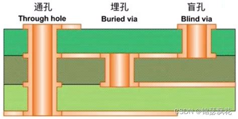
- Via barrel cracking
- Interconnect failures
The maximum operating temperature must consider both peak temperature and cycling range.
4. Design Considerations for High-Temperature Operation
4.1 Copper Weight and Trace Geometry
- Thicker copper (2 oz+) improves heat spreading
- Wider traces reduce current density and localized heating
- Thermal relief patterns prevent heat sinking during soldering
4.2 Layer Stackup Configuration
- Symmetrical stackups minimize warpage
- Even copper distribution balances thermal stresses
- Thermal vias transfer heat to inner layers or heatsinks
4.3 Surface Finishes
Common finishes and their temperature limits:
- HASL (Hot Air Solder Leveling): 260°C during application
- ENIG (Electroless Nickel/Immersion Gold): Stable to 350°C
- Immersion Silver: Limited to ~150°C continuous
- OSP (Organic Solderability Preservative): Degrades above 150°C
4.4 Component Selection and Placement
- High-power components require careful thermal management
- Adequate spacing prevents thermal interference
- Consideration of component temperature ratings
5. Testing and Qualification Standards
5.1 IPC Standards
- IPC-6012: Qualification and Performance Specification for Rigid PCBs
- IPC-TM-650: Test Methods including thermal stress tests
- IPC-4101: Specification for base materials
5.2 Common Thermal Tests
- Thermal Shock Testing (-55°C to +125°C cycles)
- Solder Float Test (288°C for 10-60 seconds)
- Thermal Aging (prolonged exposure at elevated temperature)
- TMA (Thermal Mechanical Analysis) for Tg determination
5.3 Industry-Specific Requirements
- Automotive: AEC-Q100, ISO 16750
- Aerospace: MIL-PRF-31032, DO-160
- Industrial: IEC 60068
6. Practical Applications and Temperature Ranges
6.1 Consumer Electronics
- Typical maximum: 70-85°C
- FR-4 standard material sufficient
- Compact designs challenge thermal management
6.2 Automotive Electronics
- Under-hood applications: 125-150°C
- Engine control units require high-Tg materials
- Vibration and thermal cycling considerations
6.3 Industrial Electronics
- Factory automation: up to 130°C
- Motor drives require robust thermal design
- Often need conformal coating for harsh environments
6.4 Aerospace and Defense
- Avionics: -55°C to +125°C standard
- Engine-adjacent systems may exceed 200°C
- Polyimide or ceramic substrates common
6.5 Downhole Electronics (Oil/Gas)
- Extreme environments up to 250°C
- Specialized materials required
- Hermetic packaging often necessary
7. Methods to Enhance Thermal Performance
7.1 Active Cooling Solutions
- Forced air cooling with fans
- Liquid cooling systems
- Peltier coolers for precise temperature control
7.2 Passive Thermal Management
- Heat sinks and thermal pads
- Increased copper pour areas
- Strategic component placement for natural convection
7.3 Advanced PCB Technologies
- Embedded heat pipes
- Direct bonded copper substrates
- Thick-film ceramic circuits
7.4 System-Level Design
- Proper enclosure ventilation
- Isolation of heat-generating components
- Thermal interface materials
8. Future Trends in High-Temperature PCBs
8.1 Emerging Materials
- Nanocomposite substrates with improved thermal conductivity
- Graphene-enhanced laminates
- High-temperature thermoplastic materials
8.2 Additive Manufacturing
- 3D-printed circuit structures with optimized thermal paths
- Embedded cooling channels
- Custom geometries for improved heat dissipation
8.3 Integration with Thermal Management
- Co-design of electrical and thermal performance
- Active thermal control systems
- Smart materials with temperature-adaptive properties
9. Conclusion
The maximum operating temperature of a PCB depends on a complex interplay of material properties, design choices, and operating conditions. While standard FR-4 serves most commercial applications up to about 110°C, specialized materials extend this range to 260°C or higher for extreme environments. Proper material selection, thoughtful design, and appropriate thermal management techniques allow reliable operation across virtually any temperature range required by modern electronics.
Designers must consider not just the absolute maximum temperature, but also the duration of exposure, thermal cycling effects, and the temperature-dependent behavior of all board materials and components. As electronic systems continue to push performance boundaries, advanced PCB materials and thermal management solutions will play an increasingly critical role in enabling reliable high-temperature operation.

