The Design and Implementation of a Heart-Shaped SMD LED PCB
Abstract
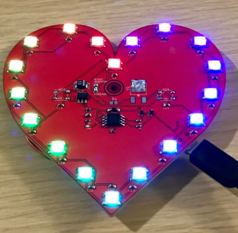
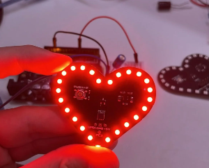
This article explores the comprehensive design process of a heart-shaped Surface Mount Device (SMD) LED printed circuit board (PCB). Covering schematic design, PCB layout, component selection, assembly techniques, and potential applications, this paper serves as a technical guide for creating aesthetically pleasing yet functional LED displays. The heart-shaped PCB demonstrates how electronic design can merge artistic form with technical function, creating products suitable for decorative lighting, gifts, and educational projects.
1. Introduction
Surface Mount Technology (SMT) has revolutionized PCB design by enabling compact, efficient, and cost-effective electronic assemblies. When applied to LED displays, SMT allows for creative shapes and patterns while maintaining excellent performance. The heart-shaped SMD LED PCB represents an intersection of electronic engineering and artistic design, suitable for various applications from decorative lighting to wearable technology.
This paper details the complete development process of such a PCB, from initial concept to final implementation, providing valuable insights for engineers, hobbyists, and designers interested in creating shaped LED displays.
2. Design Considerations
2.1 Electrical Requirements
The primary electrical considerations for a heart-shaped LED PCB include:
- Voltage and Current Requirements: Typical SMD LEDs operate at 2-3.5V forward voltage with 20mA forward current
- Power Supply Options: USB (5V), battery (3-4.5V), or wall adapter
- Current Limiting: Essential resistor calculations based on power supply voltage
- Power Consumption: Total current draw based on number of LEDs
2.2 LED Selection
Key parameters when selecting SMD LEDs:
- Package Size: 0603, 0805, or 1206 are common for hand assembly
- Color: Single color, RGB, or addressable LEDs
- Brightness: Measured in millicandelas (mcd)
- Viewing Angle: Typically 120-160 degrees for SMD LEDs
2.3 Control Options
Various control schemes can be implemented:
- Simple On/Off: Single switch control
- PWM Dimming: Variable brightness control
- Pattern Control: Microcontroller-driven light patterns
- Addressable LEDs: Individual LED control (WS2812B, etc.)
3. Schematic Design
3.1 Basic Circuit Configuration
The fundamental LED circuit consists of:
- Power source (VCC)
- Current-limiting resistor (R)
- SMD LED (D)
- Ground connection (GND)
For parallel configurations, each LED requires its own current-limiting resistor to ensure uniform brightness.
3.2 Resistor Calculation
The current-limiting resistor value is calculated using Ohm’s Law:
R = (V_source – V_LED) / I_LED
Where:
- V_source = Supply voltage
- V_LED = LED forward voltage
- I_LED = Desired LED current (typically 20mA)
3.3 Advanced Control Circuits
For dynamic displays, consider:
- Microcontroller Interface: ATtiny85, Arduino, or ESP8266
- LED Drivers: Constant current drivers for large arrays
- Wireless Control: Bluetooth or WiFi modules
4. PCB Layout
4.1 Shape Design
Creating the heart shape involves:
- Creating a vector outline of the heart shape
- Converting to PCB outline in CAD software
- Placing LEDs along the outline or filling the area
4.2 LED Placement
Key placement considerations:
- Uniform Spacing: Typically 5-15mm between LEDs
- Routing Challenges: Maintaining trace width within curved areas
- Thermal Considerations: Adequate spacing for heat dissipation
4.3 Layer Stackup
Standard configurations:
- Single Layer: Simplest design, limited routing
- Two Layer: Improved routing, ground plane
- Flex PCB: For wearable or curved applications
4.4 Routing Techniques
Special considerations for shaped PCBs:
- Curved Traces: Maintain consistent impedance
- Teardrop Pads: Improve reliability at connection points
- Via Placement: Careful placement in high-density areas
5. Manufacturing Considerations
5.1 PCB Fabrication
Key specifications:
- Board Material: FR-4 standard, aluminum for high-power
- Copper Weight: 1oz standard, 2oz for high current
- Silkscreen: White or black for contrast
- Surface Finish: HASL, ENIG, or immersion silver
5.2 Assembly Process
SMD assembly steps:
- Stencil Application: Solder paste deposition
- Component Placement: Manual or pick-and-place
- Reflow Soldering: Profile optimization
- Inspection: Visual or AOI
5.3 Design for Manufacturing (DFM)
Critical DFM checks:
- Component Clearance: Adequate spacing for assembly
- Solder Mask Bridges: Between close pads
- Test Points: For functional verification
6. Software Tools
Recommended design tools:
- Eagle: Beginner-friendly with free version
- KiCad: Open-source full-featured suite
- Altium Designer: Professional-grade tool
- Fusion 360: Integrated ECAD/MCAD
7. Assembly Techniques
7.1 Hand Assembly
For prototyping or small batches:
- Tools Required: Fine tweezers, soldering iron, flux
- Techniques: Drag soldering for multiple pins
- Inspection: Magnification for quality check
7.2 Reflow Techniques
Options for hobbyists:
- Toaster Oven: With temperature control
- Hot Plate: For single-side assembly
- Professional Reflow: Best for production
8. Testing and Troubleshooting
Essential tests:
- Continuity Check: Verify all connections
- Current Measurement: Confirm proper current limiting
- Function Test: Verify all LEDs operate
- Thermal Test: Check for overheating
Common issues and solutions:
- LEDs Not Lighting: Check polarity, solder joints
- Uneven Brightness: Verify resistor values
- Overheating: Reduce current or improve thermal design
9. Advanced Variations
9.1 RGB Versions
Implementation options:
- Common Anode/Cathode: Simplified routing
- Addressable LEDs: Individual control
- Color Mixing: PWM control for color variation
9.2 Interactive Features
Enhanced functionality:
- Touch Control: Capacitive sensing
- Motion Activation: Accelerometer-based
- Sound Reactive: Microphone input
9.3 Wearable Integration
Fashion electronics applications:
- Flexible PCB: Conforms to clothing
- Low-Profile Design: Comfortable to wear
- Battery Optimization: Extended operation
10. Applications
Potential uses for heart-shaped LED PCBs:
- Decorative Lighting: Wall art, room decoration
- Gifts and Keepsakes: Personalized presents
- Educational Tools: Electronics teaching aids
- Event Decor: Weddings, parties, celebrations
- Commercial Displays: Retail signage, advertisements
11. Conclusion
The heart-shaped SMD LED PCB demonstrates how electronic design can successfully merge aesthetic appeal with technical functionality. Through careful consideration of electrical requirements, thoughtful PCB layout, and proper manufacturing techniques, designers can create visually striking yet fully functional LED displays. This project serves as an excellent introduction to shaped PCB design while offering numerous opportunities for customization and expansion.
Future developments could incorporate more advanced control systems, wireless connectivity, and integration with smart home systems, further expanding the potential applications of these artistic electronic designs.