Impact of PCB structure on millimeter wave radar performance
Most common composite printed circuit boards (PCBs) use glass fiber as filler in their dielectric layers. However, due to the special weaving structure of glass fiber, the local dielectric constant (Dk) of the PCB board will change. Especially at millimeter wave (mmWave) frequencies, the glass weaving effect of thinner laminates will be more obvious, and local unevenness of Dk will cause significant changes in radio frequency (RF) circuit and antenna performance. A 100μm thick glass-woven polytetrafluoroethylene (PTFE) laminate was used to study the impact of its PCB structure on transmission line performance. According to the type of different glass weaving structures, the experiment found that the dielectric constant of the PCB board fluctuates between 0.01 and 0.22. In order to study the effect of different glass weave structures on antenna performance, a series-fed microstrip patch array antenna was fabricated on Rogers’ commercial laminates RO4835 and RO4830 thermoset laminates, and the results showed that the electrical performance of the antenna processed with RO4830 laminate according to normal tolerances was more consistent with the calculated value, with less variation, and had better reflection coefficient (S11 <–10dB) and boresight gain performance.
Autonomous vehicles are a current research hotspot. They can help drivers and pedestrians avoid potentially fatal accidents and require high reliability, so their component circuits must also have high reliability. Millimeter wave (mmWave) radars provide reliable and accurate solutions for target detection in autonomous driving because of their compact structure and high environmental detection sensitivity. In commercial mmWave radar systems at frequencies between 76 and 81 GHz, series-fed microstrip patch antennas are the first choice because of their easy design, compact structure, and ability to be manufactured in large quantities at low cost [1]. The higher the frequency, the smaller the wavelength, so the transmission line and antenna size at millimeter wave frequencies will be smaller than at low frequencies. In order to ensure the ideal performance of vehicle-mounted radar, it is necessary to study the impact of PCB on transmission lines and microstrip patch antennas. For millimeter wave frequency circuits that work in outdoor environments for a long time (affected by temperature and humidity) [2], the first consideration when selecting PCB circuit laminates is the consistency of material performance indicators. However, materials such as copper foil, glass fiber reinforcement, and ceramic fillers that make up the laminate will have a significant impact on the consistency of indicators at high frequencies.
This paper focuses on the impact of PCB structure on millimeter wave radar performance. The dielectric layer of most PCB laminates is usually formed by coating polymer resin on glass fiber cloth. At millimeter wave frequencies, the impact of glass fiber cloth on material performance consistency is very obvious because the width of the glass beam is comparable to the width of the transmission line. In addition, when using thinner (e.g., 100μm) PCB circuit laminates to design microstrip antennas, the glass woven cloth will cause significant changes in antenna performance and reduce processing yield.
Composition of PCB Laminates
PCB laminates are usually made by combining glass cloth with polymer resin to form a dielectric layer, and then covering it with copper foil on both sides. Glass cloth has a typical dielectric constant (Dk) of about 6.1, while the dielectric constant Dk of low-loss polymer resins is between 2.1-3.0, so there is a certain difference in Dk in a small area. Figure 1 shows a microscopic top view and cross-sectional view of the glass weave in the laminate. The circuit above the “knuckle-bundle” has a higher Dk due to the larger glass fiber content, while the circuit on the “bundle-open” has a lower Dk due to the larger resin content. In addition, the characteristics of glass weave are affected by multiple factors such as the thickness of the glass weave, the distance between the weaves, the way the weave is flattened, and the glass content in each axis.
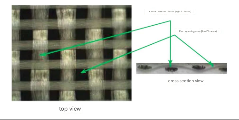
Figure 1 Microscopic top view and cross-section of glass cloth laminate
Two typical thin glass cloth weave styles are often used in thin laminates for millimeter wave applications, namely type 1080 and type 1078, as shown in Figure 2. The standard 1080 weave uses an unbalanced glass cloth, which has a higher glass content in one axis than the other axis. Compared with the 1080 weave, the 1078 open fiber glass weave has a more uniform glass fiber plane, resulting in less Dk variation across the laminate. Compared with laminates using multiple layers of glass cloth, the Dk value of single-layer glass cloth laminates varies more significantly. In addition, laminate materials with ceramic fillers can reduce the Dk variation caused by different glass cloth weaves.
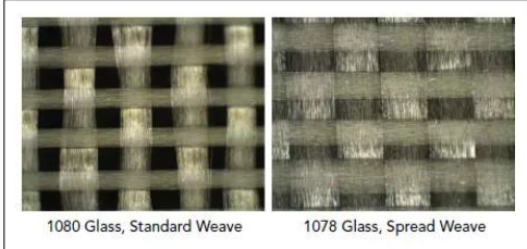
Figure 2 Microscopic view of the structure of type 1080 (open unbalanced weave) and type 1078 (open fiber) glass cloth
Impact on transmission line circuits
The test experiment used a microstrip transmission line circuit with a 1 mm termination connector. The connector was first connected to a 50 ohm grounded coplanar waveguide (GCPW), which was converted to a high impedance microstrip transmission line by an impedance transformer. As shown in Figure 3, the length of the microstrip transmission line is 2 inches, ensuring that the experimental circuit can test the effects of the glass weave structure. The circuit is processed using a thin laminate of glass woven polytetrafluoroethylene (PTFE), using rolled copper and a single layer of glass cloth. In order to compare the effects of different glass weave structures, transmission line circuits were made on three different PCB laminate structures: PTFE polytetrafluoroethylene with 1080 glass cloth, PTFE polytetrafluoroethylene with 1078 glass cloth, and ceramic-filled non-PTFE laminate with 1080 glass cloth. The processed circuits were carefully inspected, and suitable transmission lines were selected for testing, and the amplitude and phase angle characteristics of the circuits were measured. The dielectric constant change of the laminate was determined by three parameters: phase angle (phase value after expansion), group delay (based on the phase angle that varies with frequency), and propagation delay (calculated based on the phase angle).
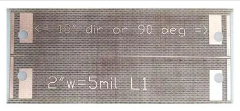
Figure 3 Microstrip transmission line with GCPW signal feed
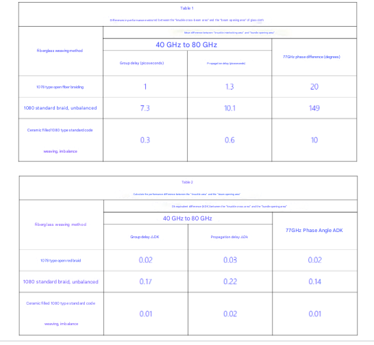
Table 1 shows the original group delay, propagation delay, and phase difference of the transmission line circuit aligned with the “knuckle beam area” and with the “beam opening area”. It can be seen that the higher the Dk value, the slower the propagation speed of the electromagnetic wave, which is consistent with the increase in group delay, propagation delay, and phase difference. Table 2 shows the calculated dielectric constant change based on the group delay, propagation delay, and phase difference of the circuit. The 1078-type open-fiber braided laminate has a uniform distribution of glass cloth, so its Dk value changes less, only 0.03, compared with the 1080-type standard braided laminate (Dk value change of 0.22). As mentioned earlier, the Dk change of ceramic-filled laminates is even smaller, only 0.02.
Impact on antenna performance
The series-fed microstrip patch antenna array is the most typical antenna used for millimeter-wave automotive radar. To study the influence of glass fiber effect on antenna performance, a 1×4 series-fed microstrip patch antenna with an operating frequency range of 76-81 GHz was designed [3]. As shown in Figure 4, the antenna was made of two different glass cloth laminate materials, RO4835 and RO4830. The antenna was made of grounded adjacent elements to study their coupling effect.
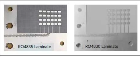
Figure 4 Series-fed microstrip patch array processed on RO4835 and RO4830 laminates
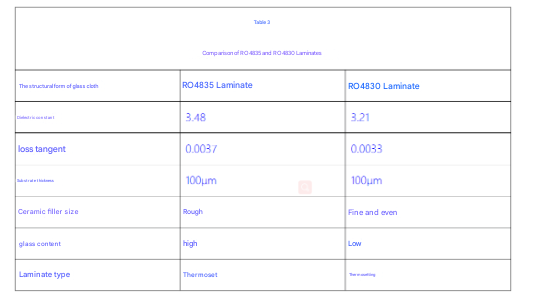
The dielectric constant of RO4835 laminate at 10 GHz is 3.48 and the loss tangent is 0.0037 (based on IPC TM-650 2.5.5.5 standard test). In addition, the dielectric constant of RO4830 laminate is 3.24 and the loss tangent is 0.0033 (based on IPC TM-650 2.5.5.5 standard test). RO4835 laminates are made of 1080 standard woven unbalanced glass fabric and ceramic filler reinforced materials. In contrast, RO4830 laminates are reinforced with 1035 flat open fiber glass weave and ceramic filler with smaller particles. Table 3 further compares the characteristics of RO4835 and RO4830 laminates.
Antennas that meet the design dimensions after processing and whose antenna transmission lines are aligned with the “knuckle beam area” and “beam opening area” of the RO4835 laminate are selected, as shown in Figures 5 (a) and (b). Since RO4830 laminates use a flat open fiber glass weave structure, it is not necessary to consider whether the conductor is aligned with the glass fabric in RO4830 laminates, as shown in Figure 5 (c). The reflection coefficient (S11) and boresight gain of the processed antennas are measured respectively.
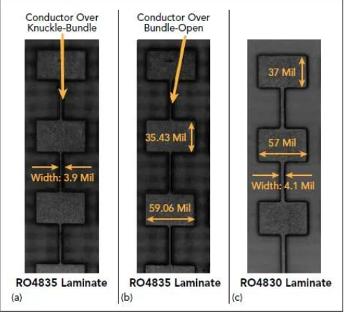
Figure 5 Antennas aligned with the “knuckle beam area” and “beam opening area” on RO4835 laminate, and antenna samples on RO4830 laminate
For simplicity, the results presented in this article are the average of test data from multiple antennas tested, and the measured results are compared with the simulation results. Figure 6 shows the test results of the antenna (five samples) on RO4835 laminate, with significant changes in the reflection coefficient (S11) and the boresight gain in the “knuckle beam area” and “beam opening area”. The performance of the antenna on RO4835 depends on the alignment of the wires with the “knuckle beam area” and “beam opening area”. In addition, the antenna gain also changes with frequency, indicating that the dielectric constant is also changing. Moreover, the shift towards high frequencies indicates a lower dielectric constant.
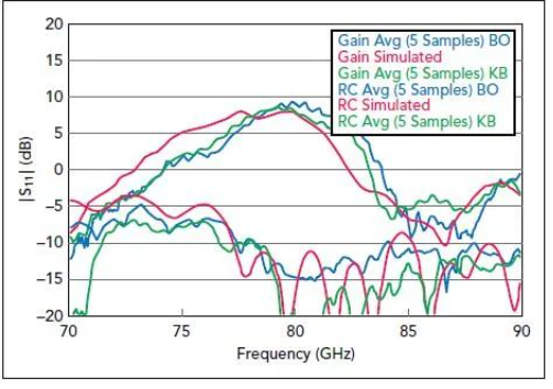
Figure 6 Comparison of measured and simulated results of antenna samples in the “knuckle beam area (KB)” and “beam opening area (BO)” of RO4835 laminate
Compared with the antenna performance on RO4830 laminate as shown in Figure 7, the antenna performance obtained by test is very consistent and more closely matches the simulated value of RO4830 laminate. The consistency between the measured results and the simulation indicates that the dielectric constant of the laminate has minimal change. Comparing the two results, the maximum change in the boresight gain in the standard woven RO4835 laminate material is 4 dB, while the maximum change in the flat open fiber woven RO4830 laminate is only 2 dB. Through such a simple experiment, it can be concluded that by using Rogers RO4830 laminates with a flat open fiber glass weave construction style, more consistent antenna performance such as reflection coefficient and boresight gain can be obtained.
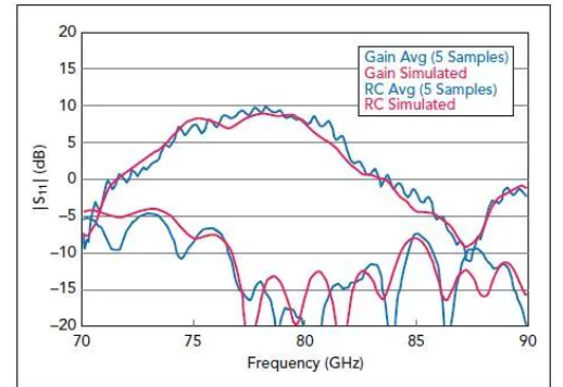
Figure 7 Comparison of measured and simulated results of antenna samples on RO4830 laminate
Conclusion
The structure of the PCB laminate affects the transmission line and antenna performance. The way the glass cloth is constructed also changes the dielectric constant on the laminate, which can reduce product performance and affect product yield. Antennas processed with RO4830 laminates have better performance consistency than RO4835 laminates. The improvement in antenna performance and processing yield is mainly attributed to the structure of the laminate material, namely: flat fiber-split glass weave, less glass content (conductor away from glass fiber), thicker substrate, etc. The improvement in antenna performance is also related to the electrical properties of the material, such as RO4830 laminates, which have lower dielectric constants and lower loss tangent values. Therefore, in the smaller wavelength millimeter-wave frequency radar applications, the performance and consistency of antennas processed with Rogers RO4830 laminates are better than those processed with RO4835 laminates.