Methods for Measuring Thermal Resistance of Printed Circuit Boards (PCBs)
Introduction
Thermal resistance is a critical parameter in the design and evaluation of printed circuit boards (PCBs), particularly as electronic devices continue to shrink in size while increasing in power density. Proper thermal management ensures reliability, performance, and longevity of electronic components. This paper explores various methods for measuring PCB thermal resistance, discussing their principles, applications, advantages, and limitations.
1. Understanding PCB Thermal Resistance
1.1 Definition of Thermal Resistance
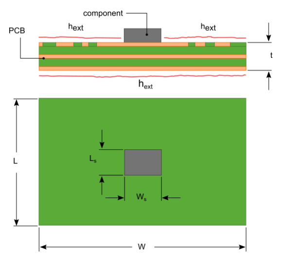
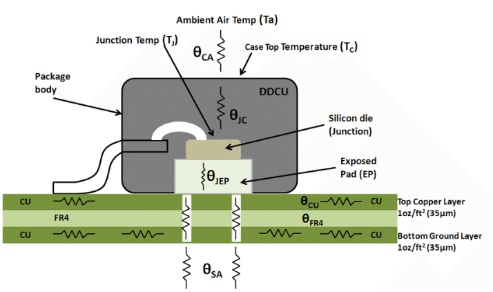
Thermal resistance (θ) in PCBs refers to the temperature difference across a material when a unit of heat power passes through it, typically measured in °C/W (degrees Celsius per watt). It indicates how effectively a PCB can conduct heat away from components.
1.2 Importance of Thermal Resistance Measurement
Accurate thermal resistance measurement helps:
- Predict component operating temperatures
- Verify thermal design effectiveness
- Identify potential overheating issues
- Optimize heat dissipation solutions
- Ensure product reliability and safety
2. Common Measurement Methods
2.1 Steady-State Method
2.1.1 Principle
The steady-state method involves applying constant power to a heat source and measuring temperature differences after the system reaches thermal equilibrium.
2.1.2 Implementation
- Mount a known heat source (e.g., power resistor) on the PCB
- Apply constant power input
- Measure temperatures at heat source and reference points using thermocouples or RTDs
- Calculate thermal resistance using: θ = ΔT/P
2.1.3 Advantages
- Simple setup and calculation
- Direct measurement
- Suitable for bulk material characterization
2.1.4 Limitations
- Long measurement time (hours for large PCBs)
- Sensitive to environmental conditions
- Difficult to isolate junction temperatures
2.2 Transient Method
2.2.1 Principle
The transient method analyzes temperature changes over time following a power step or pulse, providing both thermal resistance and capacitance information.
2.2.2 Implementation
- Apply a power step to the heat source
- Record temperature response over time
- Analyze the cooling/heating curve
- Use mathematical models (e.g., Foster or Cauer networks) to extract parameters
2.2.3 Advantages
- Faster than steady-state methods
- Provides dynamic thermal characteristics
- Can separate different thermal paths
2.2.4 Limitations
- Requires precise timing measurement
- Complex data analysis
- Sensitive to noise
2.3 Infrared Thermography
2.3.1 Principle
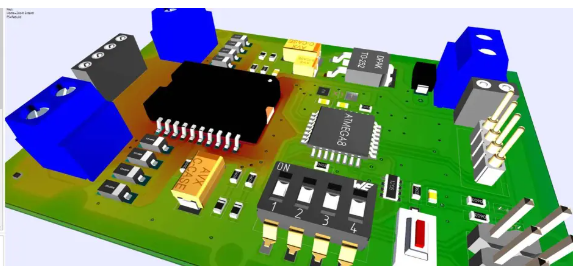
Infrared cameras measure surface temperature distributions without physical contact, allowing visualization of heat flow.
2.3.2 Implementation
- Power the device or apply external heating
- Capture thermal images at various time intervals
- Analyze temperature profiles
- Calculate thermal resistance from known power input
2.3.3 Advantages
- Non-contact measurement
- Full-field temperature data
- Visual identification of hotspots
2.3.4 Limitations
- Measures surface temperatures only
- Requires knowledge of surface emissivity
- Limited by camera resolution and accuracy
2.4 Electrical Method (Junction Temperature Measurement)
2.4.1 Principle
Uses temperature-sensitive electrical parameters (TSEPs) of semiconductor devices to determine junction temperatures.
2.4.2 Common TSEPs
- Forward voltage drop (diodes, BJTs)
- Threshold voltage (MOSFETs)
- On-resistance (power devices)
2.4.3 Implementation
- Calibrate TSEP versus temperature
- Operate device under test conditions
- Measure TSEP during operation or during brief interruptions
- Calculate junction temperature and thermal resistance
2.4.4 Advantages
- Direct junction temperature measurement
- No additional sensors needed
- Can be performed in final application
2.4.5 Limitations
- Device-specific calibration required
- May interrupt normal operation
- Accuracy depends on calibration quality
2.5 Laser Flash Method
2.5.1 Principle
A short laser pulse heats one surface of a sample, while an infrared detector measures the temperature rise on the opposite side.
2.5.2 Implementation
- Prepare flat, parallel PCB samples
- Apply laser pulse to one side
- Measure temperature response on opposite side
- Analyze time-temperature data to calculate thermal diffusivity
- Derive thermal conductivity and resistance
2.5.3 Advantages
- Fast measurement
- High accuracy for bulk materials
- Measures thermal diffusivity directly
2.5.4 Limitations
- Requires specialized equipment
- Sample preparation critical
- Limited to homogeneous materials
2.6 3-Omega Method
2.6.1 Principle
Uses a metal line (heater/sensor) patterned on the sample surface. An AC current at frequency ω generates heat at 2ω, creating a temperature oscillation at 2ω that affects resistance at 3ω.
2.6.2 Implementation
- Fabricate thin metal line on PCB surface
- Apply AC current at frequency ω
- Measure 3ω voltage component
- Analyze amplitude and phase to determine thermal properties
2.6.3 Advantages
- High sensitivity
- Measures in-plane and cross-plane conductivity
- Small measurement volume
2.6.4 Limitations
- Complex setup and analysis
- Requires sample preparation
- Limited to certain material configurations
2.7 Guarded Hot Plate Method
2.7.1 Principle
A known heat flux is applied through a sample sandwiched between heated and cooled plates, measuring temperature difference at steady state.
2.7.2 Implementation
- Place PCB sample between plates
- Apply controlled heat flux
- Measure temperature gradient
- Calculate thermal resistance
2.7.3 Advantages
- Absolute measurement (no calibration needed)
- High accuracy for homogeneous materials
- Standardized method (ASTM C177)
2.7.4 Limitations
- Large sample requirements
- Long measurement time
- Difficult for multilayer PCBs
3. Comparative Analysis of Methods
| Method | Accuracy | Speed | Complexity | Cost | Best Application |
|---|---|---|---|---|---|
| Steady-state | Medium | Slow | Low | Low | Bulk material characterization |
| Transient | High | Medium | Medium | Medium | Dynamic thermal analysis |
| Infrared | Medium | Fast | Medium | High | Hotspot identification |
| Electrical | High | Fast | Medium | Low | Junction temperature measurement |
| Laser flash | High | Fast | High | High | Thin materials, anisotropic |
| 3-Omega | Very High | Medium | Very High | Very High | Thin films, local measurements |
| Guarded hot plate | Very High | Very Slow | High | High | Standard reference measurements |
4. Practical Considerations for PCB Thermal Resistance Measurement
4.1 Sample Preparation
- Ensure representative samples
- Consider board thickness and layer stack-up
- Account for copper distribution
- Prepare clean, flat surfaces for contact methods
4.2 Environmental Control
- Minimize air currents
- Control ambient temperature
- Consider radiative effects
- Account for convection in final application
4.3 Measurement Uncertainty
Sources of error include:
- Contact resistance in thermal interfaces
- Sensor placement accuracy
- Power measurement errors
- Thermal losses to environment
- Non-uniform heat distribution
4.4 Standards and Guidelines
Relevant standards include:
- JEDEC JESD51 series for semiconductor packages
- ASTM D5470 for thermal interface materials
- IPC-TM-650 for PCB test methods
- MIL-STD-883 for military applications
5. Advanced Techniques and Emerging Methods
5.1 Thermoreflectance Imaging
- Uses temperature-dependent reflectivity changes
- High spatial resolution
- Fast measurement capability
5.2 Raman Thermometry
- Measures temperature-dependent Raman shifts
- Nanoscale resolution
- Requires transparent or thin samples
5.3 Scanning Thermal Microscopy
- AFM-based thermal probing
- Nanoscale thermal mapping
- Slow measurement process
5.4 Computational Methods
- Combining limited measurements with modeling
- Inverse heat transfer techniques
- Machine learning approaches
6. Conclusion
Accurate measurement of PCB thermal resistance is essential for reliable electronic design, with methods ranging from simple steady-state approaches to sophisticated laser-based techniques. The choice of method depends on required accuracy, available equipment, sample characteristics, and specific information needs (e.g., bulk properties versus localized measurements). As electronics continue to advance, measurement techniques are evolving to meet the challenges of miniaturization, higher power densities, and more complex thermal management solutions. A combination of experimental measurement and computational modeling often provides the most comprehensive understanding of PCB thermal performance.

