
Audio Amplifier PCB Design: Why Copper Core PCB Reduces Heat in High-Power Amps
When designing high-power audio amplifiers, thermal management is the difference between a roadworthy amp and one that cooks itself on the first gig. FR4 PCBs just don’t cut it once you push past a couple hundred watts – thermal throttling, distortion creep, and caps drying out are all signs the board can’t shed heat fast enough. Copper core PCBs fix that by pulling heat straight out of power devices and spreading it across the whole board. This guide walks through why copper core works, how to design for it, and when it’s worth the cost over aluminum or FR4.
We design metal-core boards for a living, and most audio engineers we talk to don’t realize how much headroom they’re leaving on the table with FR4.
Why Thermal Management is Critical in Audio Amplifier Design
High-power amps generate heat from multiple spots. Output MOSFETs or IGBTs dump 50–150W per channel depending on load and output level. Gate drivers switching at high frequencies add their own heat proportional to frequency and gate capacitance. Sense resistors, rectifiers, regulators – they all contribute.
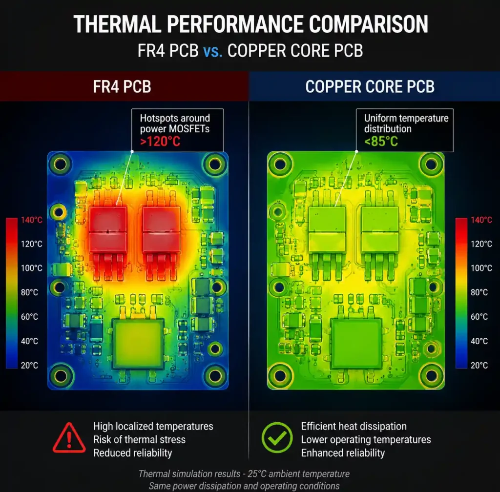
On FR4, heat pools under these components and forms hotspots. When junction temps climb past limits, bad things happen: transistor beta drifts and crossover distortion increases, thermal runaway becomes a real risk in bipolar stages, electrolytic caps age twice as fast for every 10°C rise, and solder joints crack over thermal cycles.
For pro audio where reliability is everything, thermal design can’t be an afterthought. Metal-core PCBs give you a direct thermal path from component to heatsink.
Understanding Copper Core PCB Construction
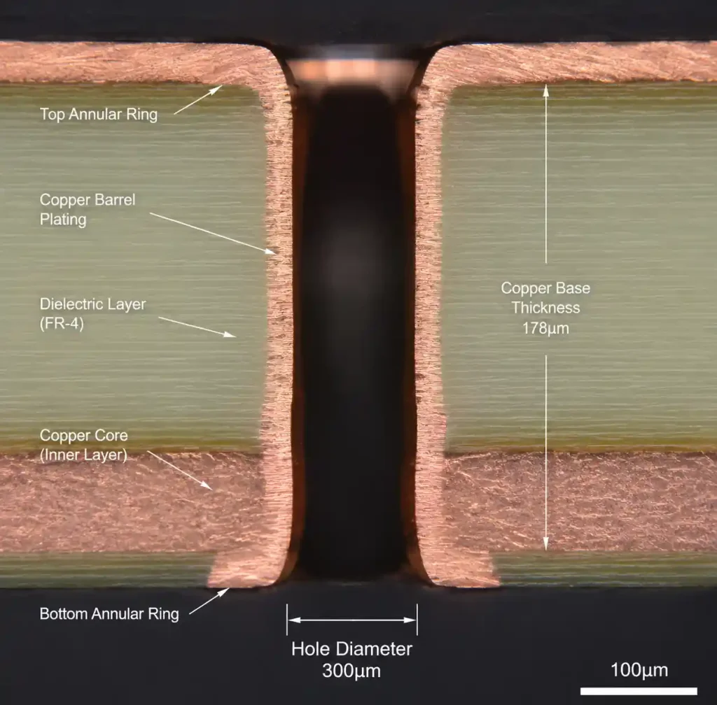
A copper core PCB substitutes the FR4 substrate with a thick copper plate – 1.0 to 3.0mm thick. The stackup goes: copper base, a thin thermally conductive dielectric (75–150μm), circuit layer (1–4oz copper), then soldermask and silkscreen.
The dielectric is the critical part. It has to isolate the circuit electrically from the grounded copper base while moving heat efficiently. Common dielectrics are ceramic-filled epoxies at 2–4 W/m·K, polyimide for higher temps, or aluminum nitride ceramics hitting 20–30 W/m·K for premium thermal performance.
The copper base itself is both mechanical support and giant heat spreader. At 385–400 W/m·K, copper conducts heat nearly twice as well as aluminum (205 W/m·K). That difference matters when you’ve got concentrated heat from power devices.
How Copper Core Reduces Heat in Audio Amplifiers
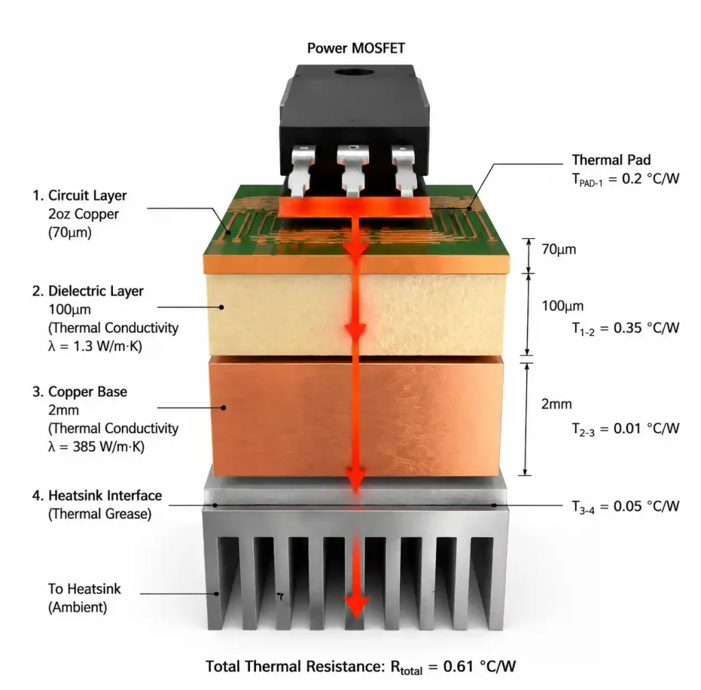
Copper core works through three mechanisms. Direct heat extraction – power transistors conduct heat through their thermal pads, through the thin dielectric (about 100μm), and into the copper base within milliseconds. The base then spreads that heat laterally across the entire board.
Lateral spreading – a 2mm copper base moves heat sideways over 100mm or more, way beyond what 2oz copper on FR4 can manage. If you’ve got multiple power devices close together, the copper base averages temperatures across the board instead of each device making its own hotspot.
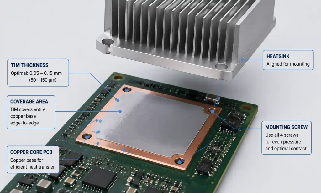
Efficient transfer to cooling – the copper base bolts directly to a heatsink or chassis with thermal interface material. Short, low-resistance path to ambient. FR4 needs thermal vias, copper pours, and indirect mounting – multiple extra thermal interfaces.
From our thermal tests, copper core PCBs drop power transistor junction temps by 30–50°C versus equivalent FR4 at the same power. That means higher reliability, smaller heatsinks, and more power in the same footprint.
Design Guidelines for Audio Amplifier Copper Core PCBs
Layout rules differ from FR4. Position power devices (MOSFETs, rectifiers) directly over the copper base with maximum thermal pad contact. Keep them away from board edges where the copper base might be reduced for mounting holes.
Thermal pad design is crucial. The pad on the circuit layer should match or exceed the device footprint to maximize heat transfer. Use 1–4oz copper in high-current zones. Via stitching isn’t needed because heat conducts straight through the dielectric to the copper base – no vias required.
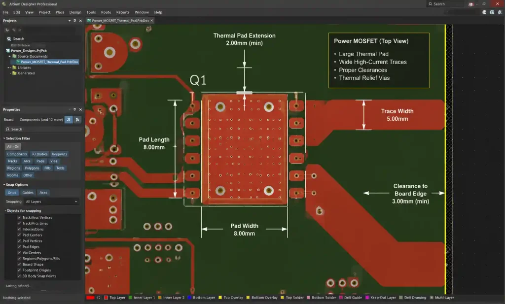
Trace width must consider both electrical and thermal limits. A 10A trace in 2oz copper needs at least 5mm width to keep voltage drop and self-heating under control. Also, the copper base is typically grounded for safety, so maintain adequate clearance to board edges. For ±70V supplies, increase clearances by 50% over IPC-2221 minimums.
Copper Core vs Aluminum Core vs FR4 – Performance Comparison
The table below shows real numbers from our lab tests and field data.
| Parameter | FR4 (2oz Cu) | Aluminum Core | Copper Core |
|---|---|---|---|
| Base thermal conductivity (W/m·K) | 0.3–0.4 | 205 | 385–400 |
| Dielectric thermal conductivity (W/m·K) | 0.3–0.4 | 2–4 | 2–4 |
| Typical dielectric thickness | 1.6mm (multi) | 75–150μm | 75–150μm |
| Junction temp reduction vs FR4 | 0°C (baseline) | 20–35°C | 30–50°C |
| Relative cost | 1.0× | 2.5–3.5× | 4.0–5.5× |
| Max continuous power density | 2–3 W/cm² | 8–12 W/cm² | 12–18 W/cm² |
Here’s how we decide which to use in real projects. Aluminum core is the best cost-performance pick for moderate amps up to 200W per channel. Copper core earns its premium above 500W per channel, in tight spaces where every square centimeter counts, or in automotive/pro applications where reliability is non-negotiable.
FR4 still works for amps below 50W per channel or Class D designs running above 90% efficiency. But once you factor in the oversized heatsinks and fans that FR4 requires at higher power, moving to metal-core often pencils out.
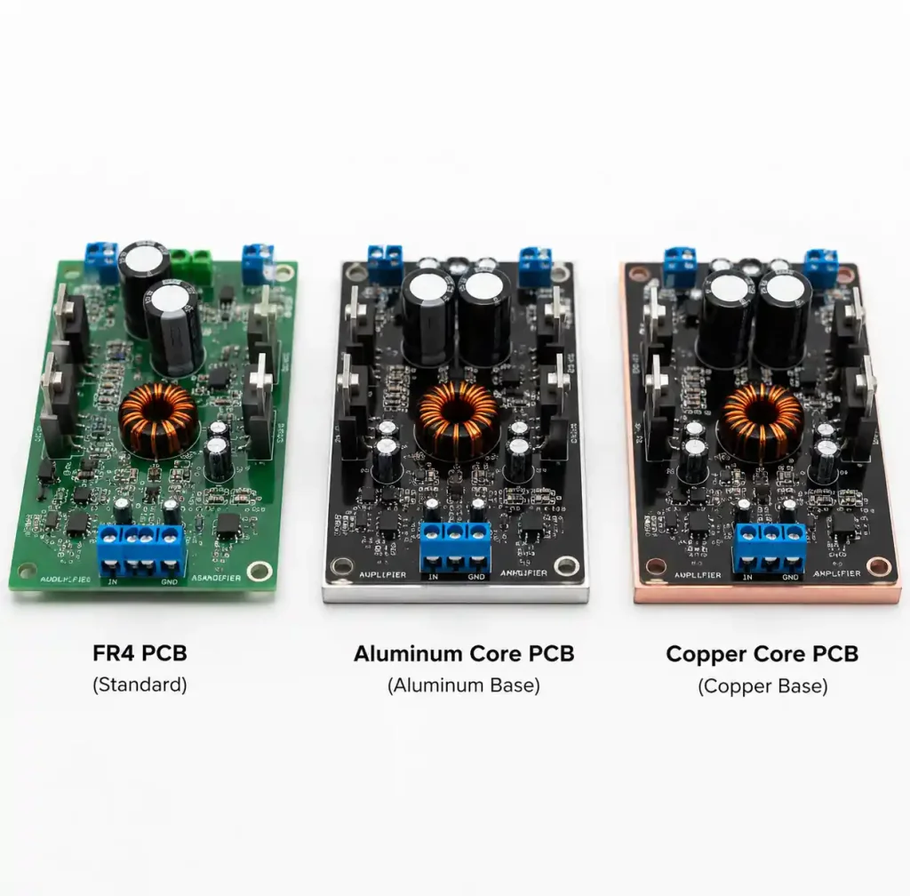
Critical Design Rules for Metal-Core Audio Amplifier PCBs
Some DFM constraints to keep in mind. Circuit layer count is typically limited to single-sided or 2-layer stackups. Multilayer metal-core boards exist but cost significantly more. That means you need to plan signal routing, ground planes, and power distribution on limited layers.
Minimum trace width and spacing depend on copper weight. For 2oz copper, most shops support 6mil trace/space. For 4oz, bump it to 8–10mil. Through-holes must go through the copper base, requiring specialized bits and slower speeds – this adds to cost and lead time. Blind and buried vias aren’t typically available, so keep via count low.
The thick copper base makes scoring and v-cutting difficult. Most fabricators use routing (milling) for depaneling. Leave 5mm tooling margin around edges and keep components away from routing paths.
Surface finish – ENIG works well on metal-core boards with good thermal cycling resistance. HASL is tricky because the thick substrate soaks up heat during leveling. OSP is cheap but has limited shelf life.
When to Choose Copper Core Over Aluminum Core
A few practical rules we use on the job. Go copper core if your amp exceeds 500W per channel (Class AB) or 1000W per channel (Class D). The thermal advantage justifies the cost through smaller heatsinks and better long-term reliability.
Choose copper for space-constrained designs where board area or heatsink volume is limited – powered subwoofers, in-wall amps, automotive systems. The higher thermal conductivity lets you dissipate more power per square centimeter.
Aluminum core is the better bet for cost-sensitive projects, mid-range power (100–400W per channel), and designs with enough board area for heat spreading even with aluminum’s lower conductivity. Most home and commercial audio amps fit this bucket.
FAQ
Q: How much more does copper core cost than FR4?
About 4–5.5× more for prototypes. Volume production (1000+ units) brings that down to 3–4×. The cost covers copper base material, specialized drilling, and longer cycle times. For high-power amps, reduced heatsink costs and better reliability usually cover the premium.
Q: Can I put SMD components on both sides?
No – standard copper core PCBs are single-sided because the copper base has no circuit layer on the bottom. Two-sided metal-core boards exist but are much more expensive and hard to find. Plan all components on one side.
Q: Do I need thermal vias on copper core?
Not for heat extraction – heat conducts straight through the dielectric to the copper base. That’s actually one of the big advantages over FR4. If you need electrical through-holes, spec them normally, but don’t waste via count on thermal management.
Q: What copper base thickness do I need for a 300W amp?
For 300W Class AB, 1.5–2.0mm base thickness gives enough thermal mass and spreading. For Class D (higher efficiency), 1.0–1.5mm often works. Thicker bases (2.5–3.0mm) help above 500W or in tight layouts, but they add cost and drilling difficulty.
Q: What dielectric thermal conductivity should I specify?
Standard epoxy dielectrics at 2–4 W/m·K work for most audio amps up to 500W. For extreme power or very tight spaces, premium ceramic-filled dielectrics at 10–20 W/m·K are available but add 30–50% cost. Talk to your fab about options.
Conclusion: Making the Right Thermal Design Choice
Copper core PCBs deliver real thermal advantages in high-power audio amp designs – 30–50°C lower junction temps than FR4, and better heat spreading than aluminum. For pro amps, high-power subwoofers, and automotive systems where reliability and power density matter, the cost premium pays back through smaller cooling solutions and fewer field failures.
When spec’ing copper core, focus on thermal pad contact area, choose the right dielectric thermal conductivity, and place components to take full advantage of the copper base’s spreading ability. Work with your PCB manufacturer early to catch metal-core DFM issues before you commit to production.
If you’re not sure whether copper core is the right move for your design, reach out with your power dissipation numbers and board size – we’ll help you run the cost-benefit analysis.