
IoT PCB Power Management: Battery Life Optimization Techniques
With 75 billion battery-powered IoT devices deployed by 2025, every microamp of leakage current translates to maintenance costs and failures. This guide covers PCB-level techniques extending battery life from weeks to years.
Understanding Real-World Power Budgets
IoT devices operate in three power states. Active mode (20-150 mA) handles sensing and transmission. Sleep mode (5-50 µA) covers 99% of operational time. Deep sleep (<10 µA) shuts down all non-essential circuits.
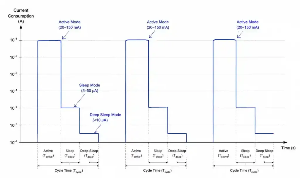
A sensor rated at 1 µA sleep current becomes 45 µA when accounting for pull-up resistors, voltage dividers, and LED circuits left powered.
Battery chemistry determines optimization strategy. Coin cells (CR2032) deliver 220 mAh at 3V, excelling at continuous draw under 1 mA but failing under pulse loads above 10 mA. Lithium-ion cells provide 2000+ mAh with excellent pulse handling. Primary lithium AA cells offer 3000 mAh for 10+ year deployments.
MCU Selection for Ultra-Low Power
Modern MCUs achieve sub-microamp sleep currents. The nRF52 draws 1.5 µA in System ON mode—exceptional for BLE nodes. STM32L4 achieves similar performance with more peripherals. ESP32-C6 improved deep sleep to 7 µA, enabling battery WiFi applications.
| MCU Family | Deep Sleep Current | Active Current (TX) | Best Application |
|---|---|---|---|
| nRF52840 | 1.5 µA | 8.8 mA (BLE) | Wearables, sensors |
| STM32L4 | 2 µA | 6 mA (no radio) | Medical devices |
| ESP32-C6 | 7 µA | 120 mA (WiFi) | Smart home hubs |
| RP2040 | 180 µA | 30 mA | Cost-sensitive |
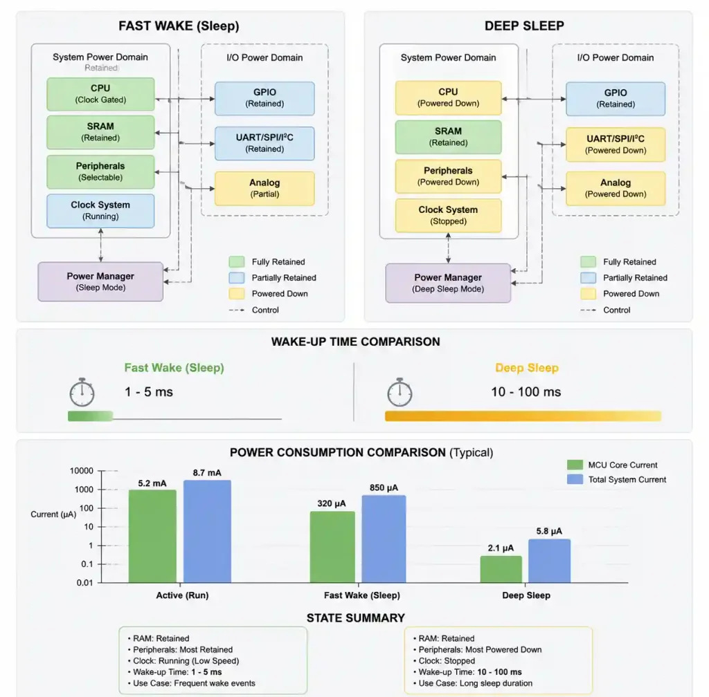
Fast wake (1-5 ms) keeps RAM powered but costs 20-50 µA. Deep sleep (10-100 ms wake) achieves sub-µA consumption but requires restoring state from flash.
Power Gating and Switched Loads
Every sensor, LED, and external circuit should sit behind a load switch. We use P-channel MOSFETs (Si2301) for loads under 100 mA, drawing <1 µA gate leakage. For higher currents, dedicated load switches like TPS22916 consume 10 nA off-state.
PCB layout determines whether load switches achieve datasheet performance. Place switches within 5 mm of MCU control pins. Route switched power rails away from always-on circuits to prevent capacitive coupling.
Sensor power sequencing prevents false readings and extends lifespan. A soil moisture sensor powered continuously draws 5 mA and electrolyzes over weeks. Power it for 100 ms every hour, and consumption drops to 0.14 µA average while extending sensor life from 3 months to 5+ years.
Energy Harvesting Integration
Solar harvesting for indoor IoT reached 32-38% efficiency in 2026, up from 15-25% two years earlier. Panels now work under 200-500 lux office lighting, offsetting sleep current. Outdoor nodes harvest 50-500 mW from small panels, supporting WiFi bursts.
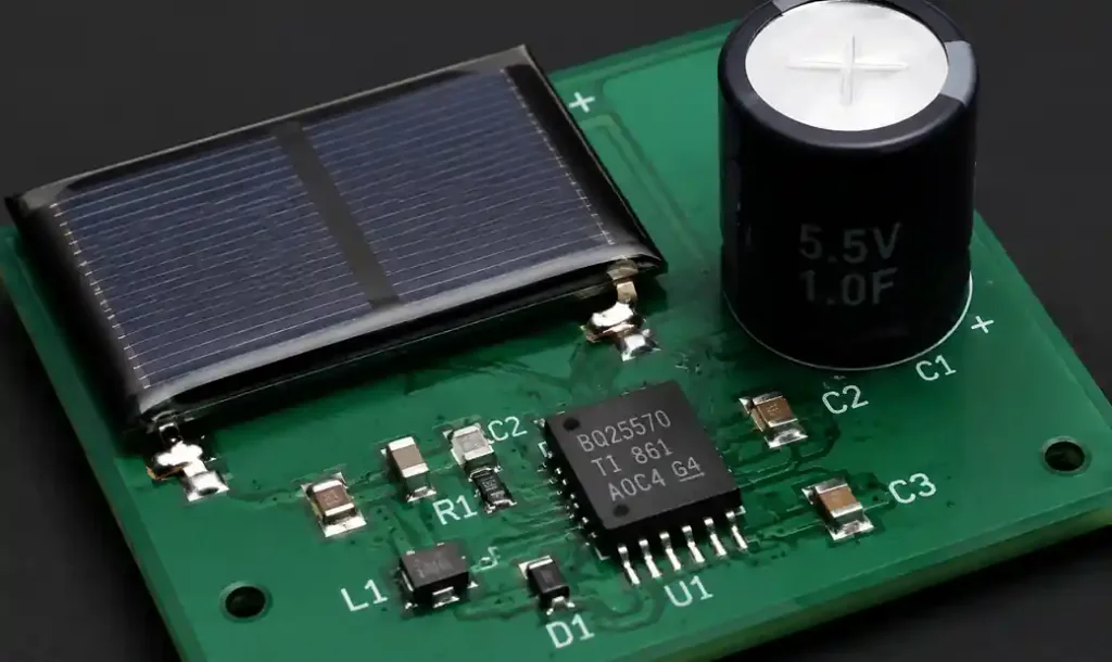
The harvesting circuit needs three components: solar panel, energy harvesting IC with MPPT (BQ25570), and storage. BQ25570 provides buck-boost charging from 100 mV input with 90% efficiency and 330 nA quiescent current. A 1 F supercapacitor stores enough energy for 50+ BLE transmissions.
Piezoelectric harvesting captures vibration from machinery, generating 10-50 µW continuous—sufficient to extend battery life 2-3x with aggressive sleep optimization. Piezoelectric harvesters excel in robustness and scalability in low-light industrial environments.
Battery Chemistry and Charging Strategy
Primary lithium cells provide longest shelf life and widest temperature range but cannot recharge. Coin cells fail under pulse loads above 10 mA—a common mistake with LoRa modules drawing 120 mA transmit bursts.
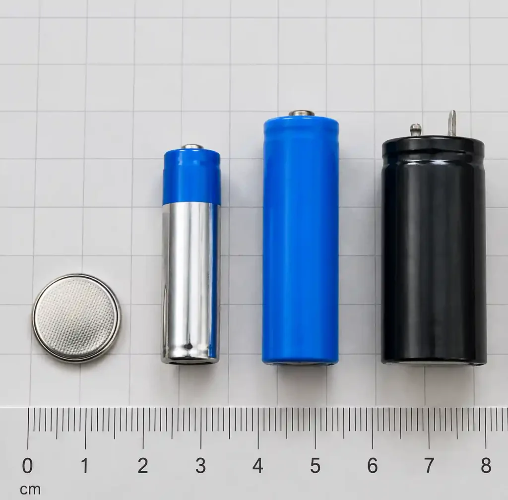
Rechargeable lithium-ion requires protection and charging management. Linear chargers (MCP73831) work for currents under 500 mA. Switching chargers (BQ24072) achieve 90%+ efficiency at higher cost. PCBs must include battery protection (DW01 + dual MOSFET).
Supercapacitors bridge batteries and capacitors. A 10 F supercapacitor stores 135 J at 3.3V—enough for 1000+ BLE transmissions. They charge in seconds, last 500,000+ cycles, and operate from -40°C to +65°C.
| Battery Type | Capacity | Pulse Current | Lifespan | Best Use Case |
|---|---|---|---|---|
| CR2032 coin | 220 mAh | <10 mA | 5-10 years | Low-power sensors |
| AA lithium | 3000 mAh | 1 A | 10+ years | Remote industrial |
| 18650 Li-ion | 2500 mAh | 10 A | 500 cycles | Rechargeable nodes |
| Supercapacitor (10F) | 9.2 mAh* | 50 A | 500k cycles | Energy harvesting |
*Effective capacity at 3.3V nominal
PCB Layout for Low-Power Operation
Ground plane integrity determines whether sleep current meets datasheet values. Use continuous ground planes under MCU and power circuits. High-frequency decoupling (100 nF) places within 2 mm of each IC power pin.
Power rail routing follows star topology from battery connector. This prevents high-current circuits from pulling down MCU supply through trace resistance. Poor routing causes 50-100 mV drops during radio transmission, triggering brownout resets that drain batteries.
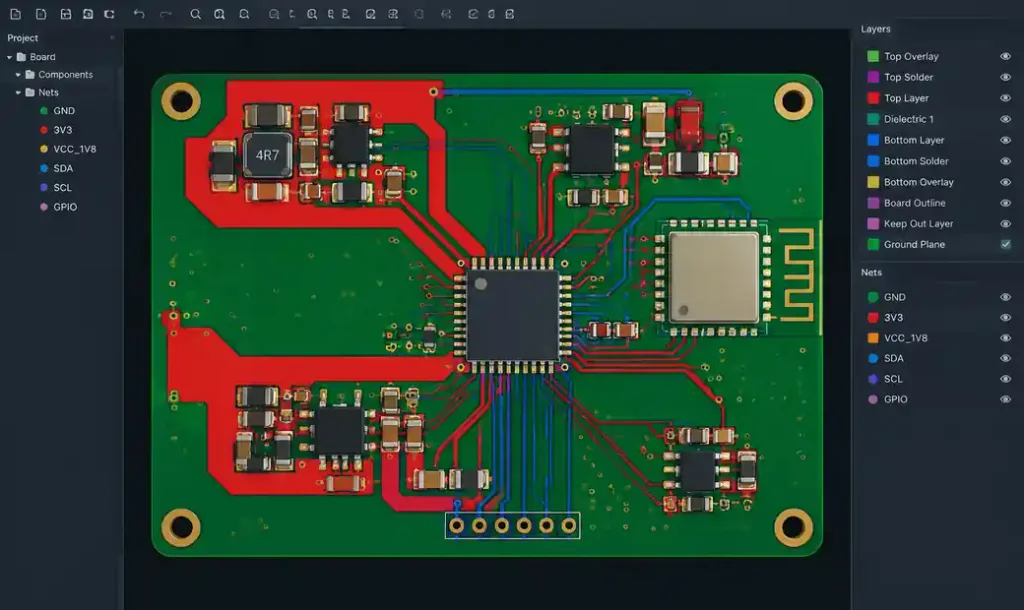
Component placement impacts leakage through board parasitics. Keep pull-up/pull-down resistors within 5 mm of associated pins. External pullups on I2C buses draw continuous current even when MCU sleeps. Switch to internal pullups (30-50 kΩ) that disconnect in deep sleep. A 10 kΩ pull-up to 3.3V draws 330 µA continuously—destroying coin cell budgets.
Firmware Power Optimization
Peripheral clock gating turns off unused timers, SPI, I2C, and ADC modules—saving 0.5-2 mA per peripheral. STM32 HAL makes this automatic with __HAL_RCC_X_CLK_DISABLE() macros. On nRF52, unused RAM blocks power down, saving 5 µA per 16 KB section.
DMA transfers eliminate polling loops. Reading 64 bytes from accelerometer takes 2 ms with blocking code at 5 mA = 10 µJ. Using DMA drops CPU involvement to 50 µs at 200 µA = 10 nJ—a 1000x improvement.
Wireless protocol choice dominates power budgets. BLE 5.0 transmits 20 bytes in 3 ms at 8.8 mA = 26.4 µJ. LoRaWAN SF7 sends 20 bytes in 80 ms at 120 mA = 9600 µJ—360x more energy.
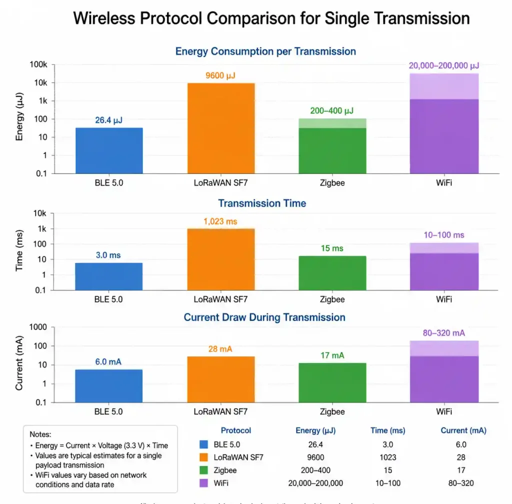
Transmission power scaling saves energy on short-range links. Running BLE at -20 dBm instead of +4 dBm reduces TX current from 8.8 mA to 3.5 mA with equivalent indoor range under 5 meters.
Measuring and Optimizing Power Consumption
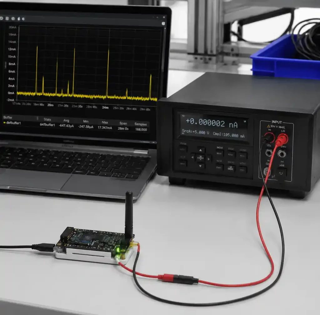
Lab measurements miss real-world leakage. We use specialized current measurement tools for precise microamp measurements over hours. Oscilloscopes with current probes show millisecond transmission bursts—critical for optimizing packet timing.
Calculate battery life from measured profiles, not datasheet averages. Sum energy per duty cycle: (sleep current × sleep time) + (active current × active time) + (TX current × TX time). A sensor sleeping 99.9% at 5 µA, active 0.05% at 3 mA, transmitting 0.05% at 120 mA averages 70 µA. A 220 mAh coin cell provides 131 days. Double sleep current to 10 µA, and life drops to 94 days—30% loss from one oversight.
Accelerated life testing validates predictions. Increase duty cycle 10x and measure consumption over 48 hours, revealing firmware bugs and thermal drift invisible in 1-hour bench tests.
PCB Material and Manufacturing
Standard FR4 provides adequate insulation for most low-power designs, but high-impedance circuits (>10 MΩ) need consideration of moisture absorption. FR4 absorbs 0.1-0.15% water, creating leakage paths at <2 mm spacing. For precision analog front-ends, specify guard rings and conformal coating. Flex PCB polyimide offers better moisture resistance for wearables.
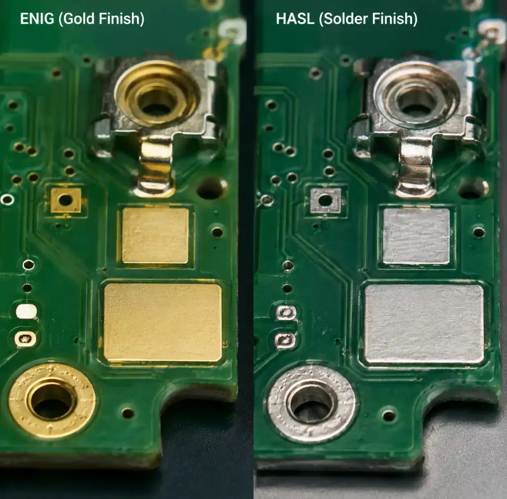
Surface finish affects contact resistance in battery clips. ENIG provides flat, non-oxidizing surfaces for reliable spring contact. HASL creates uneven surfaces—problematic for coin cell holders. Multilayer stackups reduce EMI coupling into sensor paths. A 4-layer board costs 30% more than 2-layer but provides continuous return paths.
Advanced Techniques for Sub-Microamp Design
High-impedance analog circuits leak current through PCB surface contamination. Use guard rings—copper traces surrounding high-impedance nodes driven to the same potential. A guard ring around pH probe input (>100 MΩ) reduces leakage from 200 pA to <10 pA.
Mechanical switches for hard power-off provide absolute zero consumption. A miniature slide switch costs $0.15 and eliminates shelf discharge—critical for devices stored weeks before deployment.
RTC selection impacts total sleep current. Internal RTCs keep MCU powered at 1-5 µA. External RTCs (DS3231) draw 2 µA but allow MCU to power off completely. For sensors checking conditions hourly, external RTC extends battery life 2-3x.
HDI PCB technology enables dense component placement and shorter traces in miniaturized wearables. Blind and buried vias reduce layer count while maintaining ground plane integrity.
Real-World Deployment Validation
Temperature affects battery capacity. Alkaline batteries lose 50% capacity at -20°C, while primary lithium maintains 90%. Lithium-ion charging must disable below 0°C to prevent plating causing internal shorts. Add thermistor monitoring to pause charging outside 0-45°C.
Wireless coexistence testing prevents field failures. A BLE sensor near WiFi infrastructure may retry transmissions 5-10x due to interference, multiplying battery drain. Test deployment environments with real-world RF congestion.
Field calibration accounts for component tolerances. Current sense resistors vary ±5% with temperature and aging. Battery capacity varies ±10% between manufacturers. Use one-time calibration during manufacturing. Store calibration factors in EEPROM, improving accuracy from ±20% to ±5%.
Monitor battery voltage under load to detect capacity fade. Li-ion voltage below 3.6V under 100 mA indicates <20% remaining. Transmit low-battery warnings at 25% capacity, giving 3-6 months notice for replacement.
FAQ
Q: Can I use ESP32 for coin cell operation?
ESP32 draws 10-150 µA in deep sleep—marginal for CR2032. ESP32-C6 achieves 7 µA deep sleep, viable for daily WiFi transmissions. Calculate energy: (7 µA × 86400 s) + (120 mA × 5 s) = 2.2 mAh/day. CR2032 provides 220 mAh = 100 days. Compare to nRF52 BLE achieving 500+ days.
Q: How do I prevent battery drain during storage?
Add a mechanical power switch or ship with pull-tab disconnecting battery. Even with perfect firmware, quiescent current totals 0.5-2 µA—draining coin cells in 5-10 years. A $0.15 slide switch eliminates the issue.
Q: What current measurement accuracy do I need?
For sleep current optimization, you need 0.1 µA resolution to see component-level leakage. Desktop multimeters resolve to 1 µA, missing pull-up resistors and LED leakage. Specialized tools provide nanoamp resolution.
Q: When does energy harvesting make economic sense?
A CR2032 costs $0.35, but service calls cost $15-50. If your device needs replacement within 2 years with 1000+ units deployed, spending $5 per node on solar harvesting pays back in 1-2 replacement cycles.
Q: How do I validate battery life predictions?
Run accelerated testing at 10x duty cycle for 1 week. If measured life is >90% of predicted, your model is solid. If <80%, find leakage paths—typically pull-ups, sensors, or regulators that don’t fully shut down.
Conclusion
Battery life optimization cascades through component selection, PCB layout, firmware architecture, and wireless protocol choices. Modern MCUs achieve 1.5-7 µA sleep current when surrounding circuits cooperate. Load switches power-gate sensors, dropping consumption 10-100x. Energy harvesting with 2026 solar efficiency makes indoor harvesting practical. Measure real-world consumption over full duty cycles to catch transient events. For IoT and wireless designs where battery replacement dominates maintenance costs, power optimization determines product viability.