
PCB Cleaning After Assembly: When and How to Clean Flux Residue
Flux residue accounts for 75% of post-assembly contamination issues leading to field failures in consumer electronics. During reflow and wave soldering, flux activators chemically strip metal oxides at 230-260°C, then polymerize into sticky films that attract moisture and dust. Left on the board, these residues form conductive paths that cause leakage currents exceeding 100nA—enough to drain batteries in standby mode and trigger false signals in high-impedance circuits. The decision to clean isn’t binary; it depends on flux chemistry, operating environment, and reliability requirements. Get it wrong, and you waste process time cleaning no-clean flux that posed no risk, or worse—skip cleaning water-soluble residue that corrodes traces within months.
In today’s article, we will explain when flux cleaning is mandatory versus optional, which cleaning methods match each flux type, and how to verify cleanliness meets IPC standards. This guide will help you avoid unnecessary costs while ensuring long-term reliability for your electronic assemblies.
What Flux Residue Actually Does to Your PCB
Flux residue is not inert. After soldering, activator compounds—organic acids, halides, or rosin remnants—remain on copper traces, component leads, and between fine-pitch pins. These residues are hygroscopic, meaning they absorb atmospheric moisture and form electrolytic solutions with ionic conductivity ranging from 10 to 1000 µS/cm depending on flux activity level.
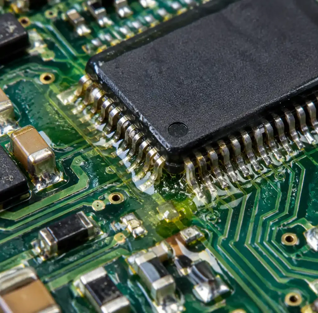
When relative humidity exceeds 60%, flux residues can create leakage paths between adjacent traces spaced 0.1-0.15mm apart. For digital circuits above 3.3V, this manifests as increased standby current. For analog sensor circuits operating in the microamp range, residue-induced leakage corrupts measurements. Battery-powered IoT devices see 20-30% shorter runtime when residue lowers the effective insulation resistance below 100MΩ.
Corrosion follows moisture absorption. Halide-activated fluxes (RA and RMA types) leave chloride ions that attack copper at rates of 2-5µm per year in humid environments. According to IPC-A-610, visible corrosion disqualifies boards from Class 2 and Class 3 acceptance criteria. You cannot repair dendrite growth—the metallized whiskers that short adjacent traces—once initiated.
When You Must Clean: Flux Type Decision Matrix
Not all flux requires removal. The IPC J-STD-004 classifies flux into three families based on post-solder residue behavior: water-soluble (requiring cleaning), no-clean (designed to remain), and rosin (historically cleaned but now often left).
| Flux Type | Ionic Content | Cleaning Requirement | Typical Application | Residue Risk if Not Cleaned |
|---|---|---|---|---|
| Water-Soluble (OA) | High (>100 µg/cm² NaCl equiv.) | Mandatory | Wave soldering, high-volume SMT | Severe: corrosion within 6-12 months, leakage current >500nA |
| No-Clean (ROL0, ROM0) | Low (<20 µg/cm² NaCl equiv.) | Optional | SMT assembly, reflow | Low: cosmetic residue, <50nA leakage |
| Rosin-Activated (RA, RMA) | Medium (50-100 µg/cm² NaCl equiv.) | Recommended | Rework, through-hole | Moderate: gradual corrosion, 100-300nA leakage |
Clean water-soluble flux within 2 hours of soldering. Activators remain water-miscible for roughly 120 minutes; after that, polymerization makes them harder to dissolve, requiring heated DI water (50-65°C) or saponifiers to break down the cross-linked residue.
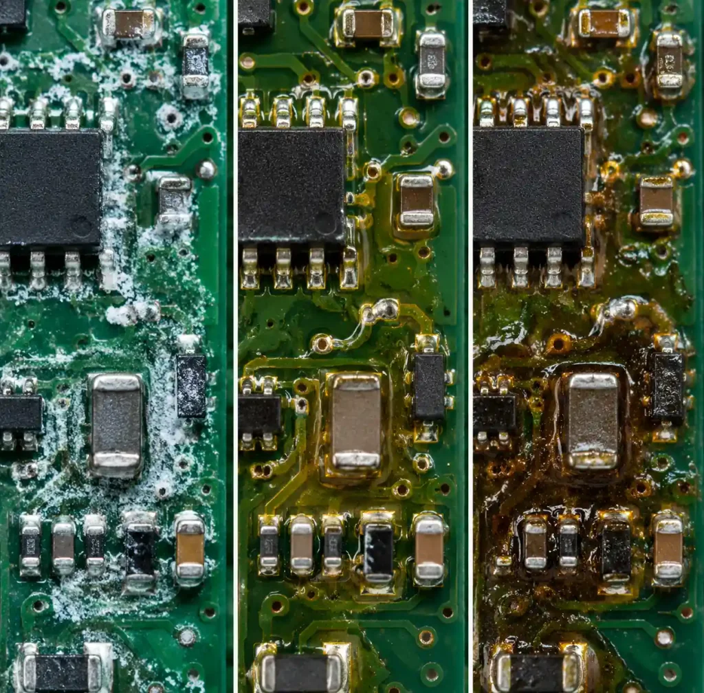
For no-clean flux, the decision hinges on application environment and circuit type. You should clean when:
- Operating voltage <3.3V with traces <0.15mm spacing (leakage risk)
- Conformal coating will be applied (trapped residue causes adhesion failure)
- High-frequency RF circuits above 1 GHz (residue alters dielectric constant)
- Medical implantable devices requiring biocompatibility
- Extended warranties in humid climates (>70% RH year-round)
Leave no-clean residue intact for consumer electronics in controlled environments, standard IoT devices, and automotive non-safety circuits where cosmetic appearance is not critical.
Cleaning Methods by Residue Type
The right cleaning method pairs solvent chemistry with flux residue composition. Water-soluble flux dissolves in polar solvents; rosin flux requires non-polar solvents; no-clean flux (when cleaned) needs semi-aqueous blends.
Isopropyl Alcohol (IPA) Batch Cleaning
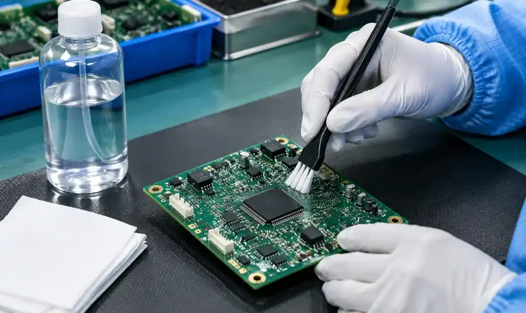
IPA at 90-99% concentration dissolves rosin flux and light no-clean residues through solvation. Apply IPA with a stiffness-rated brush (nylon or horsehair) at 45° angle to dislodge residue without damaging soldermask. Work in 100mm sections, allowing 30 seconds dwell time, then wipe with lint-free polyester wipes.
IPA evaporates completely within 60-90 seconds at room temperature, leaving no secondary contamination. However, IPA cannot remove fully polymerized water-soluble flux or ionic activators. For those, you need aqueous cleaning with deionized (DI) water and saponifiers.
Aqueous Inline Cleaning Systems
Inline aqueous systems spray heated DI water (55-65°C) mixed with 2-5% saponifier (alkaline detergent) at 20-40 psi through narrow nozzles positioned 75-100mm from the board surface. Water-soluble flux dissolves in the aqueous solution, then rinses away in the DI water cascade stage.
Three-stage systems—wash, rinse, dry—achieve <1.56 µg/cm² NaCl equivalent ionic contamination per IPC-TM-650 test method 2.3.25. Boards exit at 80-90°C, completely dry within the enclosed chamber. Aqueous systems work for high-volume production where throughput justifies capital investment ($50,000-$150,000 for inline conveyorized systems).
Ultrasonic Cleaning
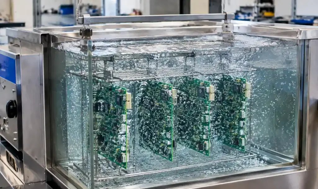
Ultrasonic tanks operating at 40 kHz generate cavitation bubbles that implode with sufficient energy to dislodge flux residue from component shadows and under low-standoff parts like QFNs and BGAs. Fill the tank with IPA, DI water + saponifier, or specialized flux removers, then submerge boards for 3-5 minutes.
Ultrasonic cleaning reaches areas manual brushing cannot—beneath 0.4mm pitch BGA balls and inside 0.3mm pitch connectors. However, excessive power (>100W/L) can damage sensitive components. Use ultrasonic for rigid-flex assemblies and high-density boards where residue hides in inaccessible geometries.
Vapor Degreasing
Vapor degreasing uses hydrocarbon or modified alcohol solvents heated to boiling (typically 60-85°C), creating vapor that condenses on cooler boards suspended above the liquid. The condensed solvent dissolves flux, drips back into the reservoir, and the process repeats until the board reaches vapor temperature (indicating cleanliness).
This closed-loop process leaves zero residue and works with heat-sensitive components. Modern vapor degreasers use low-GWP (Global Warming Potential) solvents complying with environmental regulations. Cycle time runs 4-8 minutes per batch, suitable for prototypes and small-batch production.
Cleaning Process Parameters That Actually Matter
Cleaning effectiveness depends on four variables: chemical concentration, temperature, mechanical action (agitation), and time. Optimize all four for your specific flux chemistry.
| Parameter | Water-Soluble Flux | No-Clean Flux | Rosin Flux |
|---|---|---|---|
| Solvent | DI water + 2-5% saponifier | IPA 90-99% or semi-aqueous | IPA 99% or hydrocarbon |
| Temperature | 55-65°C | 20-25°C (room temp) | 40-50°C |
| Mechanical Action | High pressure spray (25-40 psi) | Medium brush or ultrasonic | Moderate brush or vapor |
| Exposure Time | 3-5 minutes wash + 2 min rinse | 1-2 minutes per section | 2-3 minutes soak or vapor |
| Rinse Stage | Mandatory (DI water cascade) | Optional (air dry only) | Not required (evaporates) |
Temperature affects solubility exponentially—raising water temperature from 25°C to 60°C increases flux dissolution rate by 10-15x. However, exceeding 70°C risks thermal stress on components with mismatched CTEs (coefficient of thermal expansion), particularly ceramic capacitors on FR4 substrates.
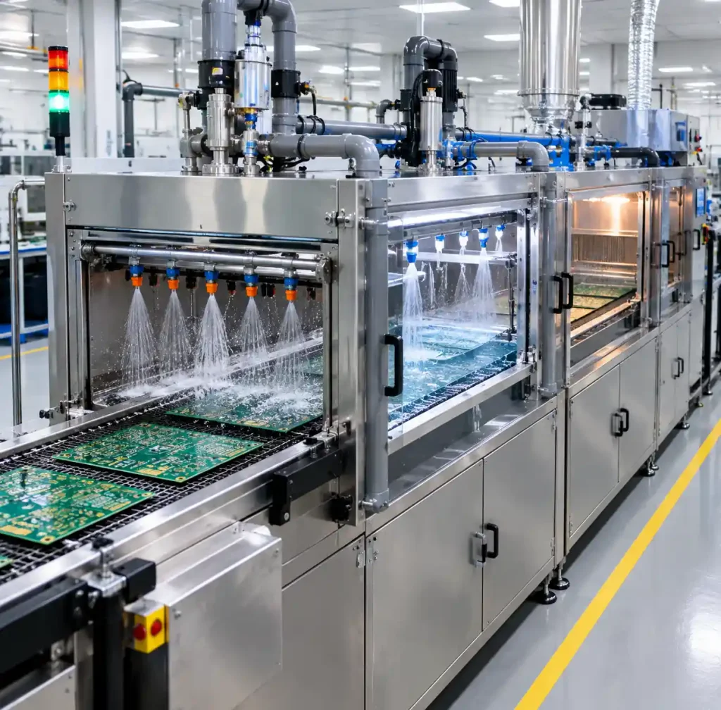
For aqueous cleaning, DI water resistivity must exceed 1 MΩ-cm. Tap water contains calcium, magnesium, and chloride ions that deposit white residue (“water spots”) on boards. These secondary contaminants mimic the ionic contamination you tried to remove. Inline systems regenerate DI water continuously through mixed-bed ion exchange resins.
How to Verify Your Board is Actually Clean
Visual inspection is insufficient. Clear boards can harbor ionic contamination below the visible threshold but above the electrical failure threshold. IPC-TM-650 test method 2.3.25 defines the resistivity of solvent extract (ROSE) test as the industry standard for quantifying cleanliness.
Extract ionic contaminants by immersing the board in 75% IPA + 25% DI water solution for 30 seconds with agitation, then measure the solution’s resistivity. Convert the reading to NaCl equivalent contamination (µg/cm²). Acceptable limits depend on product class:
- Consumer electronics: <10 µg/cm²
- Industrial/automotive: <5 µg/cm²
- Medical/aerospace: <1.56 µg/cm² (IPC Class 3)
Ion chromatography provides more detailed analysis, identifying specific contaminants (chloride, bromide, sulfate) and their concentrations. Use this method to troubleshoot cleaning process failures or validate new flux chemistries.
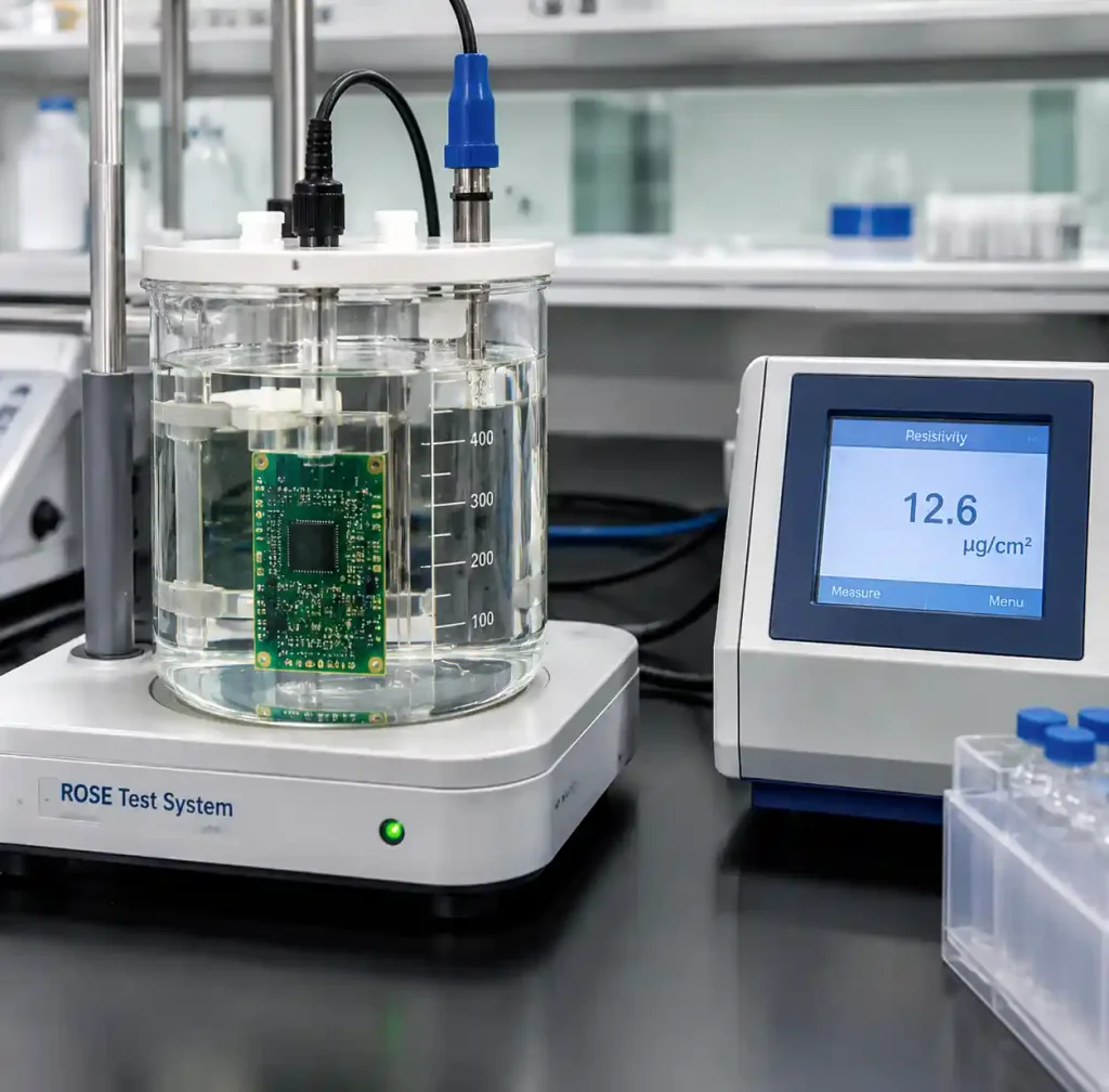
Automated inline testers perform ROSE testing at line speed (0.5-1 m/min) using microfluidic sensors that contact the board surface and inject test solution locally. Real-time feedback lets you adjust cleaning parameters before producing hundreds of contaminated boards.
When “No-Clean” Must Be Cleaned
No-clean flux is formulated to leave safe, non-conductive residue—but three conditions override that assumption and mandate cleaning anyway.
First, conformal coating. No-clean residue prevents uniform coating adhesion, creating voids where moisture penetrates. Coating manufacturers specify <5 µg/cm² ionic contamination before applying acrylic, urethane, or parylene coatings. Clean with IPA or semi-aqueous chemistry 24-48 hours before coating.
Second, high-voltage circuits above 400VDC. Even “non-conductive” no-clean residue exhibits 10⁹-10¹¹ Ω resistance—low enough to support microamp leakage at kilovolt potentials. Power electronics for EV inverters, industrial motor drives, and photovoltaic systems require residue-free boards.
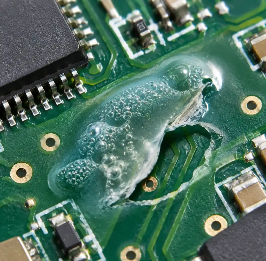
Third, electrochemical migration risk. Fine-pitch devices (<0.5mm spacing) operating in humid environments (>85% RH) with bias voltage (>3VDC) can grow metallic dendrites through no-clean residue, shorting adjacent pins in months. Clean proactively for outdoor sensors, marine electronics, and tropical-climate deployments.
Common Cleaning Mistakes That Create New Problems
Aggressive cleaning causes more failures than insufficient cleaning. Here’s what goes wrong and how to avoid it.
Using excessive brush pressure delaminates soldermask and scratches copper. Apply 200-400g force maximum—enough to flex bristles slightly without bending them. Use soft natural-hair brushes for exposed traces, stiffer synthetic brushes for soldermask-covered areas.
Incomplete rinsing leaves alkaline saponifier residue that is more conductive than the original flux. After aqueous washing, rinse with DI water spray for minimum 60 seconds at 15-20 psi until effluent resistivity matches feed water (>1 MΩ-cm). For manual cleaning, triple-rinse with fresh DI water in sequence.
Insufficient drying traps water under components, creating worse contamination than original flux. Force-air dry at 80-100°C for 5-10 minutes, directing airflow parallel to the board surface (not perpendicular) to avoid blowing droplets under low-standoff parts. Moisture-sensitive components like BGAs require baking at 125°C for 4 hours per J-STD-033 before reflow if exposed to ambient humidity >60% RH for >48 hours.
Cost-Benefit Analysis: To Clean or Not to Clean
Cleaning costs $0.15-$0.45 per board depending on process complexity, while field failures from contamination cost $8-$25 per return (including diagnostics, rework, and shipping). The break-even calculation depends on failure rate and production volume.
For consumer electronics with 1-year warranties targeting <0.5% field failure rates, no-clean processes without cleaning save $0.30/board with acceptable risk. For medical devices requiring 10-year operational life and <0.01% failure rates, aqueous cleaning adds $0.40/board but eliminates $12,000+ recall costs per incident.
Production volume shifts the equation. Inline aqueous systems with $100,000 capital cost break even at 500,000 boards/year when preventing 0.3% contamination-related failures. Below 100,000 boards/year, batch IPA cleaning or outsourced aqueous cleaning makes more economic sense.
Frequently Asked Questions
Can you skip cleaning if using no-clean flux on a prototype?
Yes, if the prototype operates in controlled indoor environments below 50% RH and doesn’t require conformal coating. For field testing or environmental qualification, clean even no-clean flux to eliminate contamination variables during troubleshooting.
How long after soldering can you still clean water-soluble flux?
Within 2 hours is optimal. After 4-6 hours, activators polymerize into cross-linked films requiring heated aqueous cleaning (60°C) or saponifiers. Beyond 24 hours, complete removal becomes difficult even with aggressive chemistry.
Does cleaning damage components?
Improper cleaning does. Ultrasonic power >100W/L can crack ceramic capacitors. IPA dissolves some conformal coatings if already applied. Aqueous cleaning above 70°C thermally stresses components. Follow component manufacturer guidelines—most MLCC and IC datasheets specify maximum cleaning temperature and chemistry.
What DI water resistivity is needed for effective rinsing?
Minimum 1 MΩ-cm, preferably 5-10 MΩ-cm for Class 3 products. Install inline resistivity monitors to verify water quality continuously. Replace DI cartridges when resistivity drops below spec—continuing with degraded water deposits ionic contaminants.
Can you clean boards after conformal coating?
No. Coating traps residue permanently. Clean before coating, or don’t coat at all. Some coatings (parylene, urethane) are removable with specialized solvents, but removal risks component damage and isn’t economically viable.
How do you clean under BGA packages?
Ultrasonic cavitation is most effective, penetrating the 0.3-0.5mm standoff gap beneath the package. Vapor degreasing also reaches these areas through capillary action. Manual IPA brushing cannot access under BGAs—use batch or inline methods for BGA assemblies.
Conclusion
Flux cleaning decisions require balancing contamination risk against process cost and complexity. Water-soluble flux demands immediate aqueous cleaning with DI rinse validation, while no-clean formulations allow selective cleaning only when conformal coating, high voltage, or extreme humidity dictates. Use ROSE testing or ion chromatography to verify cleanliness objectively—visual inspection misses ionic contamination below 5 µg/cm² that still causes field failures. For high-reliability applications, invest in inline aqueous systems that deliver <1.56 µg/cm² NaCl equivalent consistently. For moderate volumes, batch IPA ultrasonic cleaning or vapor degreasing balances thoroughness with capital cost. The wrong choice—either over-cleaning no-risk assemblies or under-cleaning corrosive residues—costs 20-80x more in field failures than implementing the right process from the start.
If you need high-reliability PCB assembly with validated cleaning processes for your electronic devices, Andwin Circuits offers complete turnkey assembly services including aqueous and IPA cleaning optimized for each flux type. Our IPC-certified technicians and inline ROSE testing ensure <1.56 µg/cm² contamination for Class 3 medical and automotive products. Contact us today for custom PCB manufacturing and assembly with guaranteed cleanliness validation.