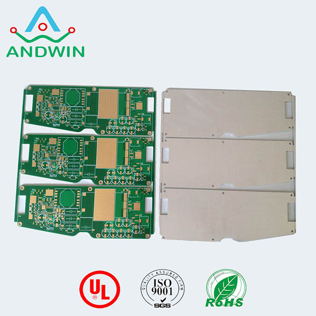
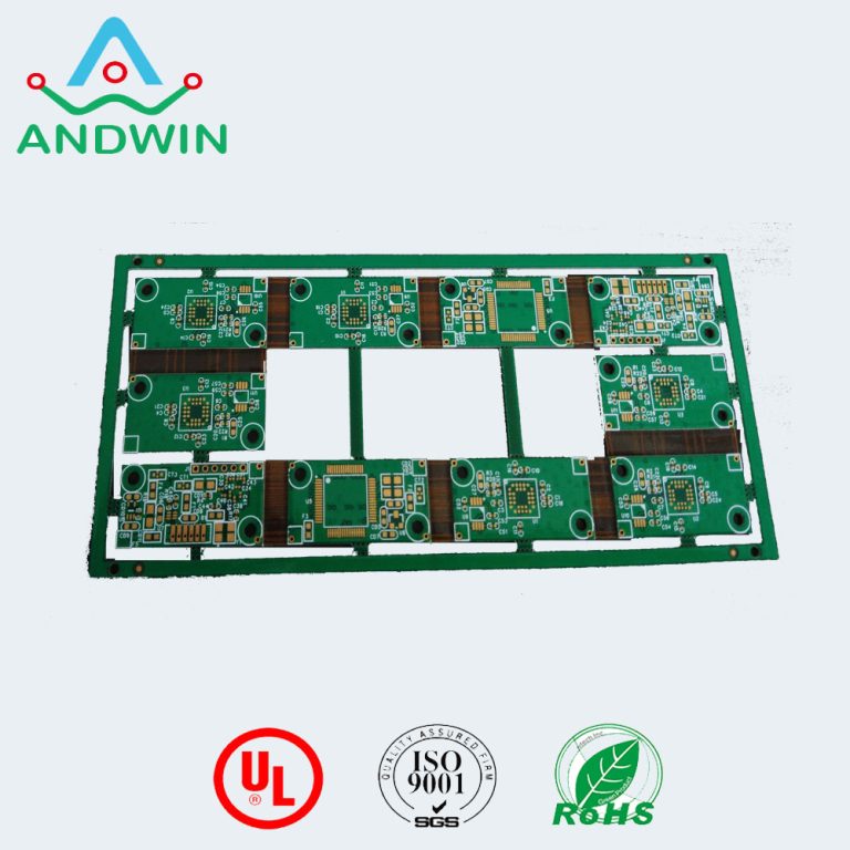
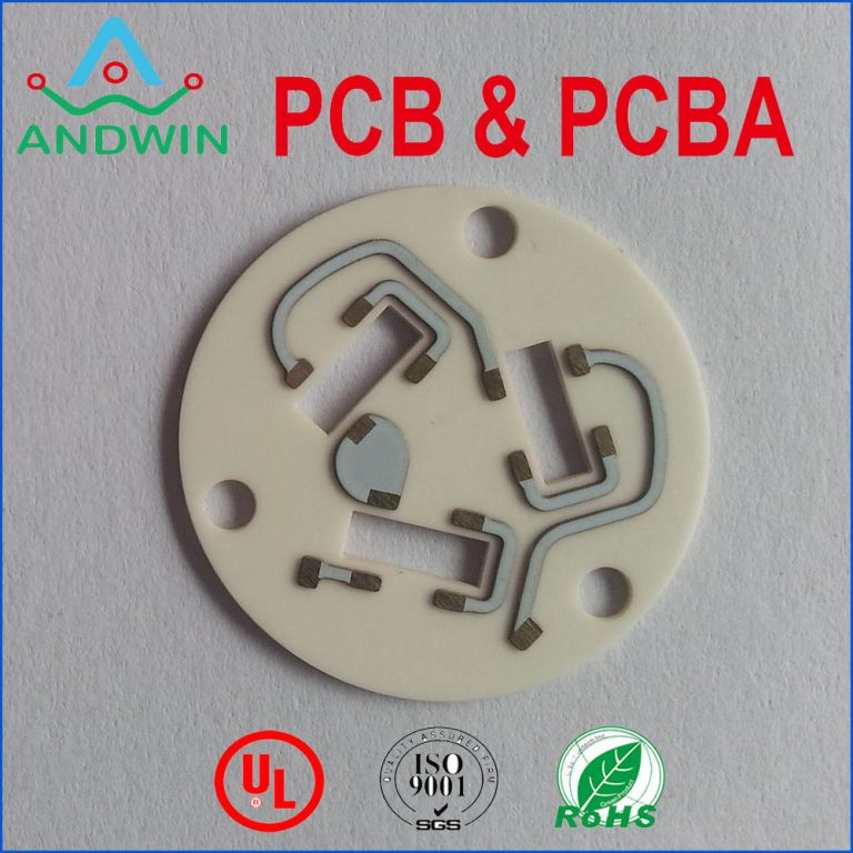
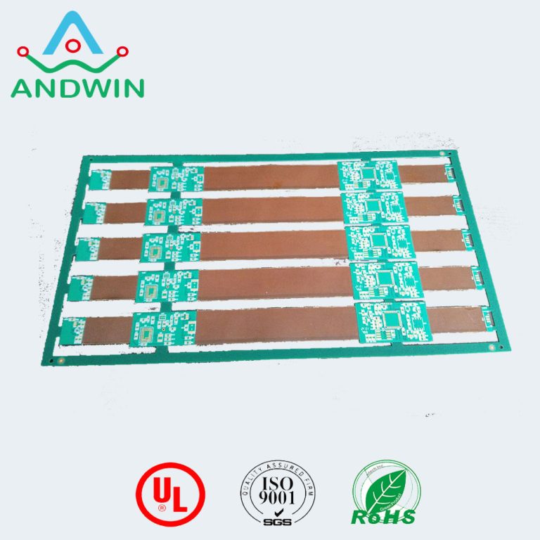
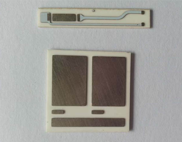
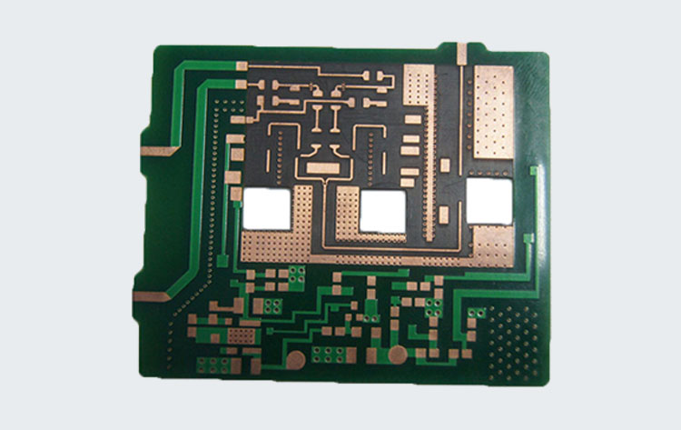
Rogers power pcb
Rogers power circuit boards can be classified based on their material composition, layer count, thickness, and other properties. Here are some common classifications:
1. Material composition: Rogers power circuit boards are typically made of high-performance materials such as Rogers 4000 series, Rogers 5000 series, and Rogers 6000 series. These materials have low dielectric loss, high thermal conductivity, and excellent electrical properties.
2. Layer count: Rogers power circuit boards can have multiple layers, ranging from 2 to 16 or more. The layer count depends on the complexity of the circuit and the required functionality.
3. Thickness: Rogers power circuit boards can be classified based on their thickness, which typically ranges from 0.2mm to 3.2mm. Thicker boards are used for high-power applications, while thinner boards are used for low-power applications.
4. Copper weight: Rogers power circuit boards can have different copper weights, which determine the current-carrying capacity of the board. Higher copper weights are used for high-power applications.
5. Surface finish: Rogers power circuit boards can have different surface finishes, such as HASL, ENIG, OSP, and immersion silver. The surface finish affects the board’s solderability and corrosion resistance.
Overall, the classification of Rogers power circuit boards depends on the specific requirements of the application and the desired performance characteristics.

The role of the Rogers power circuit board
The Rogers power circuit board plays a crucial role in the functioning of electronic devices that require a power supply.
The power circuit board is responsible for regulating the flow of electrical power from the source to the device,
ensuring that the device receives the correct voltage and current required for its operation.
The Rogers power circuit board is designed to provide high thermal conductivity, low dielectric loss,
and excellent electrical performance, which helps to ensure that the power supply is stable and reliable.
The circuit board materials used in the Rogers power circuit board are selected for their ability to withstand high temperatures,
resist moisture and chemicals, and provide excellent mechanical strength.
Overall, the Rogers power circuit board is an essential component in the power supply system,
ensuring that electronic devices receive the power they need to operate efficiently and reliably.
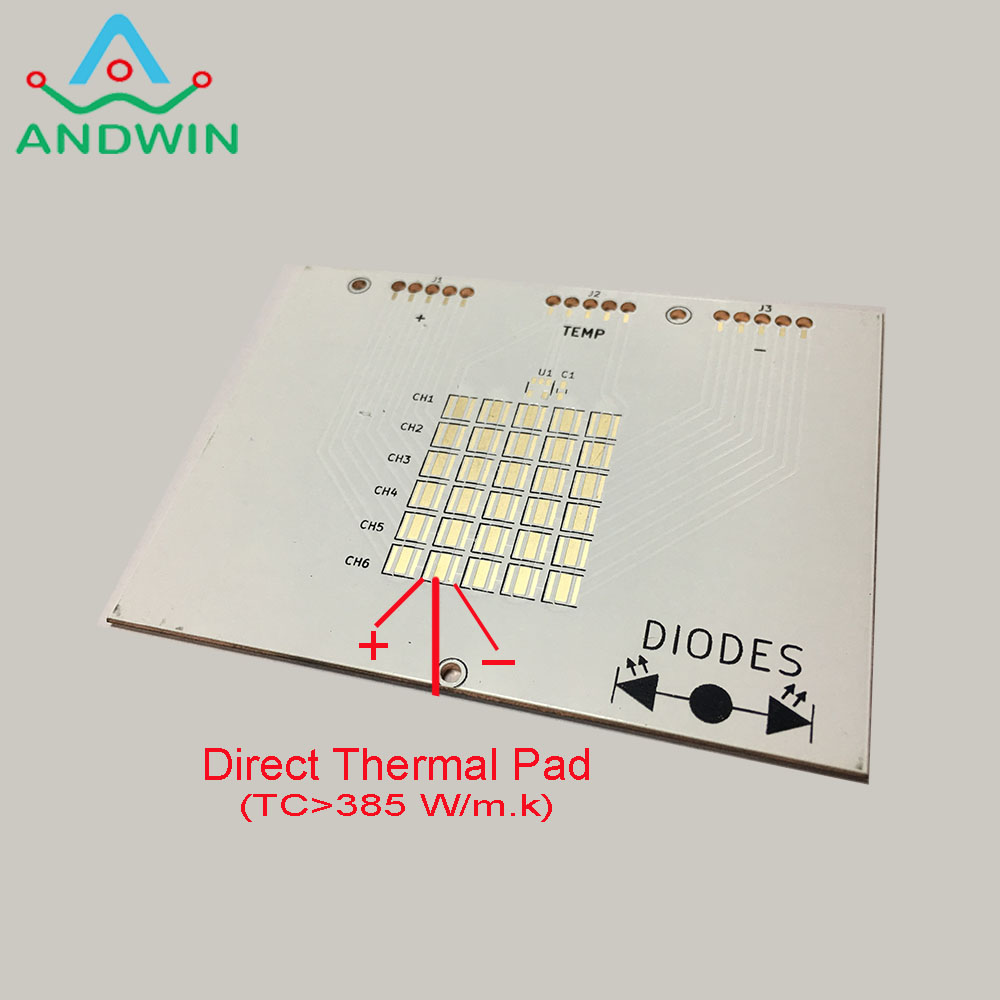
How to use Rogers power circuit board
To use a Rogers power circuit board, you will need to follow these steps:
1. Determine the power requirements of your electronic device: Before you can design a Rogers power circuit board, you need to know the power requirements of your electronic device. This includes the voltage and current requirements, as well as any other specifications that are relevant to the power supply.
2. Design the circuit board: Once you have determined the power requirements of your device, you can design the Rogers power circuit board. This involves selecting the appropriate materials, designing the circuit layout, and determining the placement of components.
3. Fabricate the circuit board: Once you have designed the circuit board, you will need to have it fabricated. This involves using specialized equipment to etch the circuit pattern onto the board and add the necessary components.
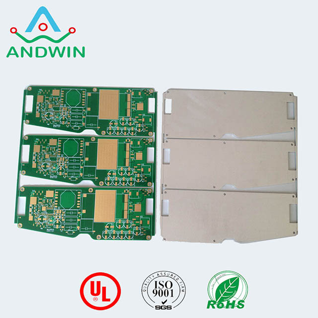
4. Test the circuit board: Before using the circuit board in your device, you will need to test it to ensure that it is functioning correctly.
This involves checking the voltage and current levels and making any necessary adjustments.
5. Install the circuit board: Once you have tested the circuit board, you can install it in your electronic device.
This involves connecting the power supply to the board and ensuring that all connections are secure.
Overall, using a Rogers power circuit board requires careful planning, design, and testing to ensure that it provides the stable and reliable power supply that your electronic device requires.

