Aerospace Printed Circuit Boards: Design, Materials, and Manufacturing Considerations
Introduction to Aerospace PCBs
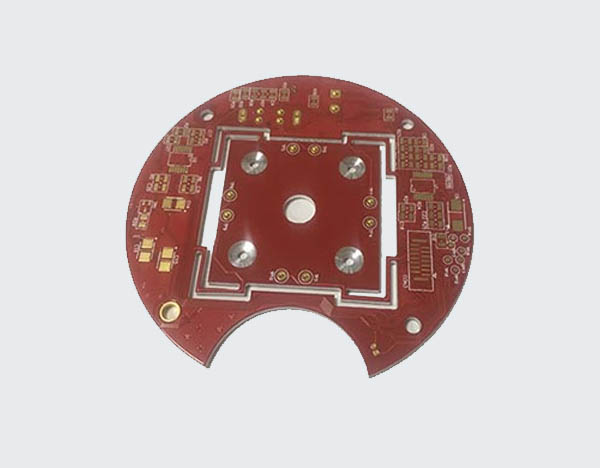
Printed Circuit Boards (PCBs) form the foundational infrastructure of modern aerospace electronics, serving as the critical interconnect platform for avionics, navigation systems, communication equipment, and flight control systems. Aerospace PCBs differ significantly from their commercial counterparts due to the extreme operating environments and mission-critical nature of their applications. These specialized circuit boards must maintain reliable performance under conditions of intense vibration, dramatic temperature fluctuations, cosmic radiation, and mechanical stress while meeting stringent weight and size constraints.
The aerospace PCB market has grown substantially in recent years, projected to reach $1.2 billion by 2026, driven by increasing aircraft production, satellite deployments, and defense spending. This growth coincides with technological advancements that allow for higher density interconnects, improved thermal management, and enhanced reliability—all essential characteristics for aerospace applications where failure is not an option.
Design Considerations for Aerospace PCBs
Reliability and Redundancy Requirements
Aerospace PCB design begins with reliability as the paramount consideration. Unlike consumer electronics where occasional failures may be tolerable, aerospace systems demand near-perfect reliability over extended operational lifetimes. Designers implement redundant circuits, fault-tolerant architectures, and rigorous testing protocols to ensure continuous operation. Critical flight systems often employ triple modular redundancy (TMR), where three identical circuits perform the same calculation simultaneously, with voting logic determining the correct output if one module fails.
Signal Integrity in Harsh Environments
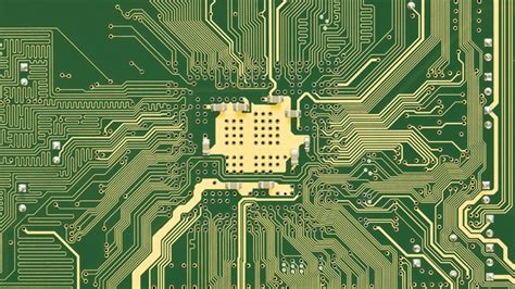
Maintaining signal integrity presents unique challenges in aerospace applications. High-speed digital signals must propagate without degradation despite potential electromagnetic interference from onboard transmitters, cosmic radiation, or atmospheric phenomena. Designers employ careful impedance matching, differential signaling, and proper grounding schemes to mitigate these issues. The use of controlled impedance transmission lines becomes crucial for high-frequency applications such as radar systems and satellite communications.
Thermal Management Strategies
Extreme temperature variations characterize the aerospace environment—from the intense cold of high altitude to the heat generated by power electronics in confined spaces. PCB designers must implement effective thermal management through:
- Strategic component placement to distribute heat loads
- Thermal vias to conduct heat away from hot components
- Selection of appropriate substrate materials with good thermal conductivity
- Consideration of conformal coatings that don’t impede heat transfer
Weight and Space Optimization
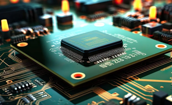
Every gram matters in aerospace applications where fuel efficiency and payload capacity are critical. PCB designers employ high-density interconnect (HDI) technologies, embedded components, and multilayer stackups to minimize weight while maximizing functionality. The use of microvias and fine-pitch components allows for dramatic size reduction without sacrificing performance.
Materials Selection for Aerospace PCBs
High-Performance Substrate Materials
The choice of substrate material significantly impacts an aerospace PCB’s performance and reliability. Common materials include:
Polyimide: The workhorse of aerospace PCBs, polyimide offers excellent thermal stability (-269°C to +400°C), radiation resistance, and mechanical durability. Its flexibility makes it ideal for applications requiring some conformability.
PTFE (Teflon): Preferred for high-frequency applications due to its low dielectric constant and loss tangent. PTFE-based laminates are commonly used in radar and satellite communication systems.
Ceramic-filled PTFE Composites: Materials like Rogers RO4000® series combine the high-frequency performance of PTFE with improved thermal conductivity and mechanical stability.
Metal Core PCBs: Aluminum or copper core boards provide exceptional heat dissipation for power electronics in aerospace applications.
Conductive Materials and Finishes
Aerospace PCBs demand conductive materials that maintain reliability over decades of service:
High-Purity Copper: Used with carefully controlled grain structure to prevent conductive pathway degradation over time.
Gold Plating: Essential for edge connectors and contacts subject to frequent mating/unmating. Aerospace specifications often call for thicker gold plating (typically 50-100 microinches) compared to commercial applications.
ENIG (Electroless Nickel Immersion Gold): A common surface finish offering good solderability and wire bondability while protecting underlying copper from oxidation.
Silver and Palladium Alloys: Used in specialized applications requiring particular conductivity or corrosion resistance properties.
Advanced Composite Materials
Emerging materials technologies are finding applications in aerospace PCBs:
Nanostructured Dielectrics: Incorporating nanomaterials like boron nitride nanotubes to enhance thermal conductivity while maintaining electrical insulation.
Graphene-enhanced Conductors: Experimental applications of graphene show promise for reducing weight while improving current-carrying capacity.
Self-healing Polymers: Materials under development that can autonomously repair minor damage from vibration or thermal cycling.
Manufacturing Processes and Quality Control
Specialized Fabrication Techniques
Aerospace PCB manufacturing employs processes that exceed standard commercial practices:
Laser Direct Imaging (LDI): Replaces traditional photolithography for higher resolution patterning, essential for HDI designs.
Plasma Etching: Provides superior control for high-frequency circuits requiring precise impedance matching.
Sequential Lamination: Used for complex multilayer boards, ensuring proper registration and material stability throughout the build-up process.
Embedded Component Technology: Allows passive components to be buried within the PCB layers, saving space and improving reliability.
Rigorous Testing Protocols
Aerospace PCBs undergo exhaustive testing to verify performance under expected operating conditions:
Environmental Stress Screening (ESS): Subjects boards to thermal cycling (-55°C to +125°C typically) and vibration profiles simulating launch or flight conditions.
Highly Accelerated Life Testing (HALT): Pushes boards beyond specification limits to identify potential failure modes and design margins.
Time Domain Reflectometry (TDR): Verifies impedance characteristics of high-speed transmission lines.
Automated Optical Inspection (AOI) and X-ray Inspection: Ensures perfect construction with no latent defects.
Certification and Documentation
Aerospace PCB manufacturers must maintain certifications including:
AS9100: The quality management standard for the aerospace industry.
IPC-6012 Class 3/3A: Defines the highest reliability requirements for rigid PCBs.
NADCAP Accreditation: For special processes like soldering and nondestructive testing.
Complete traceability of materials, processes, and testing results is mandatory, with documentation often required to be maintained for the life of the aircraft or spacecraft.
Emerging Technologies in Aerospace PCBs
Additive Manufacturing Approaches
3D printing technologies are beginning to impact aerospace PCB production:
Aerosol Jet Printing: Enables direct printing of conductive traces on complex three-dimensional surfaces, valuable for conformal electronics in aircraft structures.
Embedded 3D Printing: Allows for the creation of cavities and channels within PCBs for improved thermal management or fluidic cooling systems.
Flexible and Stretchable Electronics
New developments in flexible circuit technology are enabling innovative aerospace applications:
Conformal Flexible Circuits: Can be applied to curved surfaces within aircraft or spacecraft, reducing weight and improving aerodynamics.
Stretchable Interconnects: Important for applications where mechanical flexing occurs during operation, such as deployable space structures.
Photonic Integrated Circuits
The integration of optical interconnects with traditional PCBs offers advantages for aerospace:
Reduced Susceptibility to EMI: Optical signals are immune to electromagnetic interference.
Higher Bandwidth: Enables faster data transmission for next-generation avionics.
Weight Reduction: Fiber optics weigh significantly less than equivalent copper wiring.
AI-Enabled Design Optimization
Machine learning algorithms are being applied to aerospace PCB design:
Automated Routing Optimization: AI can determine optimal trace routing considering EMI, thermal, and signal integrity constraints.
Predictive Failure Analysis: Machine learning models trained on historical failure data can predict potential reliability issues in new designs.
Generative Design: AI systems can propose novel PCB architectures that meet performance requirements while minimizing weight and size.
Challenges and Future Directions
Radiation Hardening for Space Applications
Space-based PCBs require special consideration for:
Single-Event Effects (SEEs): Caused by cosmic rays or solar particles striking semiconductor devices.
Total Ionizing Dose (TID): Cumulative damage from prolonged radiation exposure.
Displacement Damage: Caused by high-energy particles knocking atoms out of their lattice positions.
Solutions include radiation-hardened components, error-correcting memory, and specialized layout techniques to mitigate single-event upsets.
Supply Chain and Obsolescence Management
The long service life of aerospace systems (often 20-30 years) creates challenges with component obsolescence. Strategies include:
Long-term Component Procurement: Securing lifetime buys of critical components.
Emulation and Redesign: Developing drop-in replacements for obsolete parts.
Additive Manufacturing Solutions: 3D printing of replacement interconnects or entire boards when original manufacturing capabilities no longer exist.
Environmental Regulations
Increasing environmental regulations impact aerospace PCB manufacturing:
REACH and RoHS Compliance: Restricting hazardous substances while maintaining reliability.
Sustainable Manufacturing: Reducing waste and energy consumption in production processes.
End-of-Life Considerations: Developing recycling and disposal protocols for aerospace electronics.
Integration with Structural Components
Future trends point toward deeper integration of PCBs with aircraft structures:
Structural Electronics: Where the PCB becomes part of the airframe itself.
Smart Skins: Incorporating sensors and electronics directly into aircraft surfaces.
Multifunctional Materials: Serving as both structural elements and electronic substrates.
Conclusion
Aerospace PCBs represent the pinnacle of printed circuit board technology, combining advanced materials, precision manufacturing, and rigorous quality control to meet the demanding requirements of aviation and space applications. As aerospace systems continue to evolve with increasing electrification, autonomous functionality, and connectivity demands, PCB technologies must correspondingly advance. The future of aerospace electronics will likely see greater integration of photonic and electronic circuits, wider adoption of additive manufacturing techniques, and continued innovation in materials science to push the boundaries of performance, reliability, and miniaturization. In an industry where failure carries extraordinary consequences, aerospace PCBs will remain a critical focus area for technological development and quality assurance.