Application of Aluminum PCB in LED Lighting Industry
Printed circuit boards (PCB) are ubiquitous in our technological society. Everything from computers to medical devices to cars contain these PCBs in one form or another. However, not all PCBs are the same – many of them use different designs or materials to serve unique purposes. The base material is especially important for circuit boards, which helps determine how efficiently the board transfers heat.
LED Lighting Circuit Boards
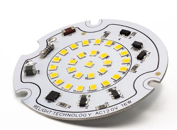
Certain applications require specific properties in their circuit boards. This is especially true for temperature-sensitive applications, one of which is LED lighting. The LED lighting industry is rapidly expanding in response to interest in more efficient and cost-effective lighting methods, but much of the functionality of LED lights depends on the temperature of their systems. For many companies, the solution to this problem is aluminum-based PCBs, which we call LED PCBs.
To help you understand why the LED lighting industry uses LED PCBs, we have outlined the nature of the PCB base layer, the appeal of aluminum PCBs, and why they work so well in the LED lighting industry.
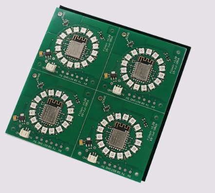
LED PCBs are now widely used in more and more applications due to its energy efficiency and environmental protection. With many years of experience in turnkey services from PCB, component procurement and OEM pcb assembly, RayMing can you provide LED PCB, LED chip and OEM LED PCB assembly services. If you have some questions about LED PCB
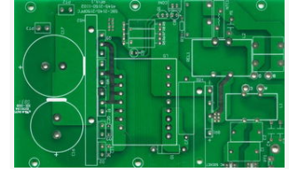
PCB Core
Engineers design printed circuit boards to work best in their specific applications. The design may specify the nature of the circuit, the PCB coating material, the size of the PCB, and a variety of other qualities. However, one of the most basic changes is the core of the circuit board.
PCB bases come in a variety of materials, including:
FR-4: The most common of these materials is FR-4, a substrate composed of glass and epoxy. Although flame retardant, FR-4 tends to be relatively inefficient in terms of heat transfer.
Epoxy: Another, though less common, PCB substrate is a material called epoxy. Although not as durable as other options, epoxy-based PCBs are much less expensive to manufacture.
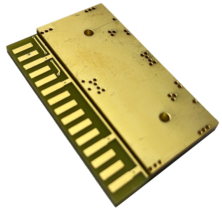
Metal Core: Metal core PCBs are very effective for a variety of applications, especially those involving heat transfer. These substrates are made of a laminate of metal (usually aluminum) and copper. These metals provide the circuit board with better electrical insulation and thermal conductivity. When thermal mass is not as important, FR-4 or epoxy substrates are more common because they tend to be relatively cheap. However, when thermal mass is important to the proper function of the final product, a metal core printed circuit board may be the solution.
How to Make an LED Board or LED Circuit Board?
Making an LED (Light Emitting Diode) circuit board is a great exercise for those who are new to electronics. It does not require many components or expertise, and it is a useful circuit. When making an LED PCB, LED circuit board, you should be familiar with how circuit boards work. The columns of holes are electrically connected with the exception of the first and last rows of holes. The first and last rows of holes (not columns) are electrically connected and slightly offset from the main grid. This characteristic of the circuit board makes the job of building an LED circuit board much simpler.
Things You Need
Circuit Board
9 Volt Battery
1″ Wire, 2 pieces
100 Ohm Resistor
LED
Instructions for Making an LED Circuit Board or LED Circuit Board
- Wrap one end of the first wire around the positive terminal of the 9 Volt battery.
- Insert the other end of the first wire into the hole of the circuit board located in the first row and first column.
- Insert one end of the 100 Ohm resistor into the same row as the wire, but this time in the second column of the circuit board.
- Place the other end of the 100 Ohm resistor into the hole of the circuit board located in the second row and second column.
- Insert the anode (long wire) of the LED into the hole located in the third row, second column of the circuit board.
- Insert the cathode (short wire) of the LED into the hole located in the third row, third column of the circuit board.
- Wrap one end of the second wire around the negative terminal of the 9 Volt battery.
- Insert the other end of the second wire into the hole of the circuit board located in the fourth row, third column. You now have a complete LED circuit board and your LEDs will light up.