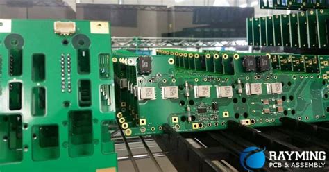
base materials for high speed high frequency pcb boards
Choosing the Right Dielectric Material for High-Speed PCBs
When designing high-speed, high-frequency printed circuit boards (PCBs), the selection of base materials is a critical factor that significantly influences the performance and reliability of the final product.
The dielectric material, which serves as an insulating layer between conductive traces, plays a pivotal role in determining the signal integrity, impedance control, and overall electrical performance of the PCB.
As the demand for faster data transmission and higher operational frequencies continues to grow, engineers must carefully evaluate the properties of various dielectric materials to ensure optimal functionality.
One of the primary considerations when choosing a dielectric material for high-speed PCBs is the dielectric constant (Dk).
The dielectric constant, also known as relative permittivity, measures the material’s ability to store electrical energy in an electric field. A lower dielectric constant is generally preferred for high-frequency applications because it reduces signal propagation delay and minimizes signal loss.
Materials such as polytetrafluoroethylene (PTFE), commonly known as Teflon, exhibit low dielectric constants and are often used in high-frequency PCB designs. PTFE’s excellent electrical properties make it suitable for applications requiring minimal signal distortion and high signal integrity.
In addition to the dielectric constant, the dissipation factor (Df) is another crucial parameter to consider. The dissipation factor quantifies the dielectric material’s inherent energy loss as heat when subjected to an alternating electric field. A lower dissipation factor indicates that the material has lower dielectric losses, which is essential for maintaining signal strength and reducing thermal issues in high-speed circuits. Materials like Rogers RO4000 series and Isola’s FR408HR are known for their low dissipation factors, making them ideal choices for high-frequency applications where signal integrity is paramount.
Thermal stability is also a key factor in selecting dielectric materials for high-speed PCBs.
As electronic devices operate at higher frequencies and power levels, they generate more heat, which can affect the performance and longevity of the PCB. Materials with high glass transition temperatures (Tg) and low coefficients of thermal expansion (CTE) are preferred because they can withstand thermal cycling and maintain their mechanical and electrical properties over a wide temperature range. For instance, materials like polyimide and certain ceramic-filled laminates offer excellent thermal stability, making them suitable for high-speed, high-frequency applications that require robust performance under varying thermal conditions.
Moreover, the choice of dielectric material can impact the manufacturability and cost of the PCB.
While advanced materials like PTFE and ceramic-filled laminates offer superior electrical and thermal properties, they can be more challenging to process and may require specialized manufacturing techniques.
This can lead to higher production costs and longer lead times. Therefore, engineers must balance performance requirements with practical considerations such as ease of fabrication and budget constraints. In some cases, high-performance epoxy-based materials like FR-4 with enhanced electrical properties may provide a cost-effective alternative for certain high-speed applications.
In conclusion, selecting the appropriate dielectric material for high-speed, high-frequency PCBs involves a careful evaluation of various factors, including the dielectric constant, dissipation factor, thermal stability, and manufacturability. By understanding the trade-offs and benefits of different materials, engineers can make informed decisions that optimize the performance and reliability of their PCB designs. As technology continues to advance, the development of new dielectric materials will further enhance the capabilities of high-speed electronic systems, enabling faster data transmission and more efficient operation in a wide range of applications.

Comparing FR4 and Rogers Materials for High-Frequency PCB Applications
When designing high-speed, high-frequency printed circuit boards (PCBs), the choice of base materials is crucial to ensure optimal performance. Two of the most commonly considered materials for such applications are FR4 and Rogers materials. Understanding the differences between these two can significantly impact the efficiency and reliability of the final product.
FR4 is a widely used material in the PCB industry, known for its versatility and cost-effectiveness.
It is a composite material made from woven fiberglass cloth with an epoxy resin binder that is flame resistant. While FR4 is suitable for a broad range of applications, its performance at high frequencies is limited. The dielectric constant (Dk) of FR4 typically ranges from 4.5 to 4.8, which can lead to signal integrity issues at higher frequencies. Additionally, FR4 has a higher dissipation factor (Df), meaning it exhibits greater signal loss, which is detrimental in high-speed applications.
In contrast, Rogers materials are specifically engineered for high-frequency applications.
Rogers Corporation offers a variety of laminates, such as RO4000, RO3000, and RT/duroid series, each designed to meet specific performance criteria. These materials have a lower dielectric constant, typically ranging from 2.2 to 3.5, which helps maintain signal integrity by reducing signal delay and distortion. Furthermore, Rogers materials exhibit a lower dissipation factor, resulting in minimal signal loss and better performance at high frequencies.
Another critical aspect to consider is thermal management.
High-speed, high-frequency PCBs often generate significant heat, and the base material’s ability to dissipate this heat is vital. FR4 has a relatively low thermal conductivity, which can lead to overheating and potential failure of the PCB. On the other hand, Rogers materials generally offer better thermal conductivity, ensuring efficient heat dissipation and enhancing the overall reliability of the PCB.
Moreover, the mechanical properties of the base materials also play a significant role in the performance and durability of the PCB. FR4 is known for its mechanical strength and rigidity, making it suitable for a wide range of applications. However, it can be prone to warping under high thermal stress. Rogers materials, while also mechanically robust, are designed to withstand the thermal and mechanical stresses associated with high-frequency applications, providing better dimensional stability and reliability.
Cost is another factor that cannot be overlooked. FR4 is more cost-effective compared to Rogers materials, making it an attractive option for budget-conscious projects
. However, the initial cost savings may be offset by the potential performance limitations and reliability issues in high-frequency applications. Investing in Rogers materials, although more expensive, can lead to better performance, reduced signal loss, and increased longevity of the PCB, ultimately providing better value in high-speed, high-frequency applications.
In conclusion, while FR4 is a versatile and cost-effective material for general PCB applications, its limitations at high frequencies make it less suitable for high-speed, high-frequency designs. Rogers materials, with their lower dielectric constant, lower dissipation factor, better thermal management, and superior mechanical properties, offer significant advantages for such applications. Therefore, when designing PCBs for high-frequency applications, it is essential to carefully consider the specific requirements and choose the appropriate base material to ensure optimal performance and reliability.
The Role of Copper Foil in High-Speed PCB Performance
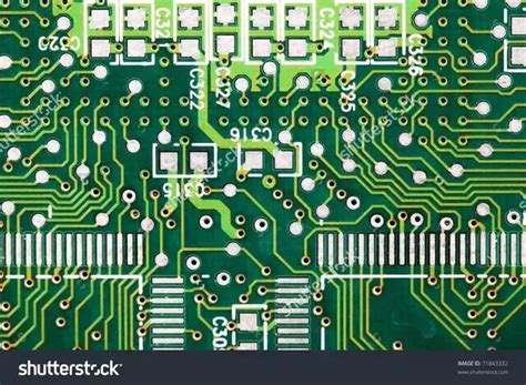
In the realm of high-speed, high-frequency printed circuit boards (PCBs), the choice of base materials is paramount to achieving optimal performance. Among these materials, copper foil plays a critical role, significantly influencing the electrical properties and overall functionality of the PCB. As the demand for faster and more efficient electronic devices continues to escalate, understanding the role of copper foil in high-speed PCB performance becomes increasingly essential.
Copper foil serves as the conductive layer in PCBs, facilitating the transmission of electrical signals between various components. Its inherent properties, such as high electrical conductivity and excellent thermal dissipation, make it an indispensable material in the fabrication of high-speed PCBs. The thickness and quality of the copper foil directly impact the signal integrity and the board’s ability to handle high-frequency signals. Consequently, selecting the appropriate type of copper foil is crucial for ensuring that the PCB meets the stringent requirements of modern electronic applications.
One of the primary considerations when choosing copper foil for high-speed PCBs is its surface roughness.
The surface roughness of the copper foil can significantly affect the signal loss and impedance control of the PCB. A smoother copper surface reduces signal attenuation and minimizes the skin effect, which is the tendency of high-frequency currents to concentrate near the surface of the conductor. This, in turn, enhances the signal integrity and ensures that the PCB can operate efficiently at high frequencies. Therefore, manufacturers often opt for low-profile or very-low-profile copper foils to achieve the desired performance characteristics.
In addition to surface roughness, the adhesion properties of copper foil are also critical.
Strong adhesion between the copper foil and the dielectric substrate ensures the mechanical stability and reliability of the PCB. Poor adhesion can lead to delamination, which compromises the electrical performance and longevity of the board. To address this, manufacturers employ various treatments and bonding techniques to enhance the adhesion of copper foil to the substrate. These treatments not only improve the mechanical bond but also contribute to the overall thermal management of the PCB, which is vital for high-speed applications.
Furthermore, the purity and composition of the copper foil are essential factors that influence the electrical performance of high-speed PCBs.
High-purity copper foils exhibit lower electrical resistance, which is crucial for minimizing signal loss and maintaining signal integrity at high frequencies. Impurities in the copper can introduce unwanted resistance and variability, leading to performance degradation. Therefore, manufacturers prioritize the use of high-purity copper foils to ensure consistent and reliable performance in high-speed applications.
Moreover, the thickness of the copper foil is another critical parameter that affects the performance of high-speed PCBs.
Thicker copper foils provide better current-carrying capacity and improved thermal dissipation, which are essential for handling the increased power demands of high-speed circuits. However, thicker foils can also introduce challenges in terms of signal integrity and impedance control. Therefore, a careful balance must be struck between the thickness of the copper foil and the specific requirements of the application to achieve optimal performance.
In conclusion, copper foil plays a pivotal role in the performance of high-speed, high-frequency PCBs. Its surface roughness, adhesion properties, purity, and thickness are all critical factors that influence the electrical and thermal characteristics of the board. As electronic devices continue to evolve and demand higher speeds and frequencies, the selection and optimization of copper foil will remain a key consideration for PCB manufacturers. By understanding and addressing these factors, manufacturers can ensure that their high-speed PCBs meet the rigorous demands of modern electronic applications, delivering reliable and efficient performance.
Thermal Management Solutions for High-Frequency PCB Boards
Thermal management is a critical consideration in the design and performance of high-frequency printed circuit boards (PCBs). As electronic devices continue to evolve, the demand for high-speed, high-frequency PCBs has surged, necessitating advanced thermal management solutions to ensure reliability and efficiency. The base materials used in these PCBs play a pivotal role in managing heat dissipation and maintaining optimal performance.
One of the primary challenges in high-frequency PCB design is the generation of heat due to the rapid switching of signals.
This heat, if not properly managed, can lead to thermal stress, component failure, and reduced overall performance. Therefore, selecting the appropriate base materials is essential for effective thermal management. Traditional materials such as FR-4, while cost-effective and widely used, may not always meet the thermal and electrical requirements of high-frequency applications. Consequently, engineers often turn to advanced materials that offer superior thermal conductivity and stability.
Polytetrafluoroethylene (PTFE) is one such material that has gained prominence in high-frequency PCB applications.
PTFE, commonly known by the brand name Teflon, exhibits excellent dielectric properties and low loss characteristics, making it ideal for high-speed signal transmission. Additionally, PTFE has a high thermal conductivity, which aids in efficient heat dissipation. However, PTFE’s mechanical properties can pose challenges during the manufacturing process, necessitating specialized techniques and equipment.
Another material that has garnered attention is ceramic-filled hydrocarbon.
This composite material combines the benefits of ceramics and hydrocarbons, resulting in a substrate with low dielectric constant and low loss tangent. The ceramic fillers enhance the thermal conductivity of the material, allowing for better heat management. Moreover, ceramic-filled hydrocarbon materials are more mechanically stable than PTFE, simplifying the manufacturing process and improving the overall reliability of the PCB.
In addition to PTFE and ceramic-filled hydrocarbon, liquid crystal polymer (LCP) is another advanced material used in high-frequency PCB applications.
LCPs offer a unique combination of low dielectric constant, low loss tangent, and excellent thermal stability. These properties make LCPs suitable for high-speed, high-frequency circuits where thermal management is crucial. Furthermore, LCPs exhibit low moisture absorption, which is beneficial in maintaining consistent electrical performance in varying environmental conditions.
While selecting the appropriate base material is fundamental, other thermal management techniques can complement the inherent properties of these materials. For instance, the use of thermal vias, which are plated through-holes that facilitate heat transfer from the PCB surface to the inner layers or heat sinks, can significantly enhance thermal performance. Additionally, incorporating heat spreaders or thermal pads can further aid in dissipating heat away from critical components.
Moreover, the design and layout of the PCB itself can influence thermal management.
Strategic placement of components, adequate spacing, and the use of thermal reliefs can help in minimizing hotspots and ensuring even heat distribution. Advanced simulation tools can assist engineers in predicting thermal behavior and optimizing the PCB design accordingly.
In conclusion, effective thermal management is indispensable for the performance and reliability of high-frequency PCBs.
The selection of appropriate base materials such as PTFE, ceramic-filled hydrocarbon, and liquid crystal polymer plays a crucial role in managing heat dissipation. Complementary techniques like thermal vias, heat spreaders, and optimized PCB design further enhance thermal performance. As the demand for high-speed, high-frequency electronic devices continues to grow, ongoing advancements in materials and thermal management solutions will be essential in meeting the evolving requirements of these applications.