Battery PCB Board: Design, Functionality, and Applications
Introduction
Printed Circuit Boards (PCBs) are essential components in modern electronics, providing a platform for electrical connections between components. In battery-powered systems, the Battery PCB Board plays a crucial role in managing power distribution, charging, protection, and monitoring. This article explores the design, functionality, and applications of battery PCB boards, highlighting their importance in various industries.
1. What is a Battery PCB Board?
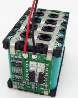
A Battery PCB Board (or Battery Management PCB) is a specialized circuit board designed to control and manage rechargeable or non-rechargeable battery systems. It ensures safe operation, efficient power delivery, and longevity of the battery by integrating protection circuits, charging controllers, and monitoring systems.
Key Functions of a Battery PCB Board
- Power Regulation: Maintains stable voltage and current output.
- Overcharge/Over-discharge Protection: Prevents battery damage.
- Short-Circuit Protection: Safeguards against electrical faults.
- Temperature Monitoring: Prevents overheating.
- Battery Balancing: Ensures uniform charging in multi-cell batteries (e.g., Li-ion packs).
- Communication Interface: Enables data exchange with external devices (e.g., via I2C, SPI, or UART).
2. Design Considerations for Battery PCB Boards
Designing a battery PCB requires careful planning to ensure safety, efficiency, and reliability. Below are critical factors to consider:
A. Battery Chemistry Compatibility
Different battery types (Li-ion, LiPo, NiMH, Lead-acid) require specific PCB designs due to varying voltage levels, charging protocols, and safety requirements.
B. Current Handling Capacity
- Trace width and copper thickness must support the required current without excessive heating.
- High-current applications may require thicker copper layers (e.g., 2oz or 4oz).
C. Protection Circuitry
- Voltage Protection ICs: Prevent overcharging (e.g., DW01 for Li-ion).
- Current Sensors: Detect overcurrent conditions.
- Thermal Management: Heat sinks or thermistors for temperature control.
D. PCB Layout Best Practices
- Minimize Loop Areas: Reduces electromagnetic interference (EMI).
- Proper Grounding: Avoids noise and voltage fluctuations.
- Component Placement: Critical ICs (e.g., BMS chips) should be near the battery terminals.
E. Communication Protocols
- Some battery PCBs include UART, I2C, or CAN bus for communication with microcontrollers or host systems.
3. Types of Battery PCB Boards
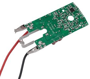
A. Single-Cell Battery PCBs
- Used in small devices (e.g., wearables, Bluetooth earphones).
- Basic protection features (overcharge, over-discharge, short-circuit).
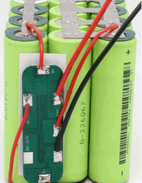
B. Multi-Cell Battery Management Systems (BMS)
- For high-capacity batteries (e.g., electric vehicles, power tools).
- Includes cell balancing to ensure uniform charge distribution.
C. Charger Control PCBs
- Manages charging cycles (CC/CV for Li-ion).
- Often integrates USB-PD or Qi wireless charging.
D. Smart Battery PCBs
- Includes fuel gauges (e.g., MAX17048) for battery level monitoring.
- Communicates with host devices for advanced power management.
4. Applications of Battery PCB Boards
Battery PCBs are used across various industries due to their critical role in power management.
A. Consumer Electronics
- Smartphones, laptops, tablets.
- Wireless earbuds and smartwatches.
B. Electric Vehicles (EVs) & E-Bikes
- High-voltage BMS for Li-ion battery packs.
- Ensures safe charging/discharging in automotive environments.
C. Medical Devices
- Portable medical equipment (e.g., insulin pumps, portable monitors).
- Requires high reliability and safety certifications.
D. Renewable Energy Systems
- Solar battery storage systems.
- Manages charge from solar panels to battery banks.
E. Industrial & IoT Devices
- Wireless sensors and IoT modules.
- Long-life battery management for remote applications.
5. Challenges in Battery PCB Design
A. Thermal Management
- High currents can cause overheating; proper heat dissipation is crucial.
- Use of thermal vias, heatsinks, or active cooling.
B. Miniaturization
- Shrinking PCB size while maintaining functionality (common in wearables).
- Requires high-density interconnect (HDI) techniques.
C. Safety Compliance
- Must meet standards like UL 2054, IEC 62133, or UN 38.3 for transport safety.
D. Cost vs. Performance Trade-offs
- High-performance BMS increases cost; optimizing for budget without compromising safety is key.
6. Future Trends in Battery PCB Technology
A. Integration with AI & IoT
- Smart BMS with predictive analytics for battery health monitoring.
B. Flexible & Stretchable PCBs
- For next-gen wearables and foldable electronics.
C. GaN & SiC-Based Power Electronics
- Higher efficiency and faster charging in EV applications.
D. Wireless BMS (wBMS)
- Eliminates wiring in large battery packs (e.g., Tesla’s structural battery packs).
Conclusion
Battery PCB boards are indispensable in modern electronics, ensuring safe and efficient power management across various applications. From small wearable devices to large electric vehicle battery systems, these PCBs play a pivotal role in performance, safety, and longevity. As technology advances, battery PCBs will continue to evolve, incorporating smarter, more efficient, and more compact designs to meet the growing demands of next-generation electronics.
By understanding the design principles, challenges, and emerging trends, engineers can develop robust battery management solutions that push the boundaries of innovation in power electronics.


