Breadboard vs. PCB: A Comprehensive Comparison
Introduction
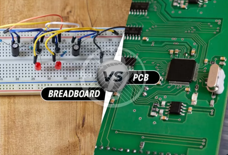
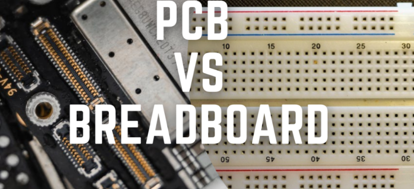
In the world of electronics prototyping and circuit design, two primary platforms dominate the landscape: breadboards and printed circuit boards (PCBs). Both serve as foundations for building and testing electronic circuits, but they differ significantly in their construction, usage, and applications. This 2000-word article explores the key differences between breadboards and PCBs, examining their advantages, disadvantages, and ideal use cases to help electronics enthusiasts, students, and professionals make informed decisions about which platform to use for their projects.
Understanding Breadboards
What is a Breadboard?
A breadboard is a reusable solderless device used for prototyping electronic circuits. It consists of a plastic board with a grid of holes into which components and wires can be inserted. The holes are electrically connected in specific patterns, typically in rows and columns, allowing for quick circuit assembly and modification.
Types of Breadboards
- Solderless Breadboards: The most common type, featuring spring-loaded contacts that grip component leads.
- Solderable Breadboards (Perfboards): Similar layout but require soldering components in place.
- Mini Breadboards: Smaller versions for compact projects.
- Breadboard Modules: Specialized breadboards with built-in power supplies or common components.
Breadboard Internal Structure
The typical solderless breadboard contains:
- Two sets of “power rails” running vertically on each side
- Horizontal rows in the center with typically 5 connected holes each
- A central divider separating the two sides
- Metal clips beneath the plastic housing that make electrical connections
Understanding PCBs
What is a PCB?
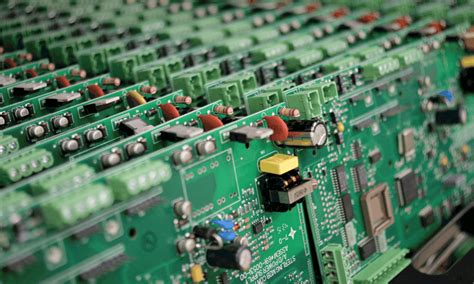
A printed circuit board (PCB) is a permanent platform for electronic circuits where copper tracks are laminated onto a non-conductive substrate to create electrical pathways between components. PCBs are designed using specialized software and manufactured through an industrial process.
Types of PCBs
- Single-layer PCBs: Conductors on only one side of the substrate.
- Double-layer PCBs: Conductors on both sides of the substrate.
- Multi-layer PCBs: Three or more conductive layers separated by insulation.
- Flexible PCBs: Made with flexible plastic materials.
- Rigid-Flex PCBs: Combination of rigid and flexible sections.
- High-Frequency PCBs: Designed for RF applications.
PCB Construction
A standard PCB consists of:
- Substrate (typically FR-4 fiberglass)
- Copper layers (1oz or 2oz thickness common)
- Soldermask (protective coating)
- Silkscreen (component labels and markings)
- Vias (conductive holes connecting layers)
- Pads (connection points for components)
Breadboard vs. PCB: Key Comparisons
1. Ease of Use and Prototyping Speed
Breadboard Advantages:
- Instant circuit assembly without soldering
- Easy modifications and component swapping
- No design software required
- Immediate testing capability
PCB Advantages:
- Requires design time (CAD software)
- Manufacturing lead time (hours to weeks)
- Changes require board redesign
- Better for finalized designs
2. Circuit Complexity and Size
Breadboard Limitations:
- Practical for small to medium complexity circuits
- Limited by available space and connection points
- Difficult to implement high-density components
- Challenging for surface-mount devices (SMDs)
PCB Advantages:
- Handles highly complex circuits
- Scalable from tiny to very large designs
- Accommodates high component density
- Supports all package types including SMDs
3. Electrical Performance
Breadboard Drawbacks:
- Higher parasitic capacitance and inductance
- Contact resistance issues (typically 0.1-1Ω per connection)
- Susceptible to noise and crosstalk
- Limited high-frequency performance (typically <10MHz)
PCB Advantages:
- Controlled impedance possible
- Lower parasitic effects
- Consistent contact resistance
- Better high-frequency performance
- Proper grounding and shielding options
4. Mechanical Reliability
Breadboard Issues:
- Temporary connections prone to loosening
- Vulnerable to vibration and movement
- Limited mechanical stress tolerance
- Wires can accidentally disconnect
PCB Strengths:
- Permanent soldered connections
- Robust mechanical structure
- Can withstand vibration and stress
- Suitable for end products
5. Cost Considerations
Breadboard Economics:
- Low initial cost (basic boards $5-$50)
- Reusable components
- No manufacturing costs
- Cost-effective for prototyping
PCB Economics:
- Higher initial investment
- Design software costs (or learning curve)
- Manufacturing costs (though decreasing)
- Economical at scale
- Lower per-unit cost for production
6. Longevity and Durability
Breadboard Shortcomings:
- Temporary solution
- Contacts wear out over time
- Not suitable for permanent installations
- Environmental vulnerability
PCB Advantages:
- Designed for long-term use
- Can last years or decades
- Environmental protection options
- Suitable for field deployment
7. Aesthetics and Professionalism
Breadboard Appearance:
- Messy wire arrangements
- Amateurish appearance
- Difficult to document
- Not suitable for product demos
PCB Advantages:
- Clean, professional layout
- Customizable appearance
- Easier documentation
- Presentable for demonstrations
When to Use a Breadboard
Ideal Breadboard Applications
- Learning Electronics: Perfect for students understanding circuit fundamentals.
- Concept Proofing: Quick verification of circuit ideas.
- Component Testing: Evaluating new parts or configurations.
- Temporary Demonstrations: Classroom or workshop examples.
- Algorithm Development: For microcontroller projects before PCB design.
- Circuit Experimentation: Trying different configurations rapidly.
Breadboard Best Practices
- Keep wire runs short to minimize noise
- Use color-coded wires for better organization
- Regularly check connections for tightness
- Avoid high-current or high-voltage applications
- Clean periodically to maintain good contacts
- Use breakout boards for SMD components
When to Use a PCB
Ideal PCB Applications
- Final Product Design: For manufactured goods.
- High-Frequency Circuits: RF, high-speed digital.
- Compact Designs: Space-constrained applications.
- Reliability-Critical Systems: Medical, automotive, aerospace.
- Mass Production: Economies of scale.
- Harsh Environments: Moisture, temperature, vibration.
PCB Design Tips
- Start with thorough schematic design
- Follow good layout practices (ground planes, etc.)
- Consider design for manufacturability (DFM)
- Verify with design rule checks (DRC)
- Order prototypes before full production
- Document all design decisions
Transitioning from Breadboard to PCB
The Prototyping Process
- Concept Development: Initial idea formulation.
- Breadboard Prototype: Proof of concept.
- Schematic Design: Formal circuit documentation.
- PCB Layout: Component placement and routing.
- Prototype Fabrication: First physical PCB.
- Testing and Iteration: Refining the design.
- Production: Final manufacturing.
Tools for the Transition
- Circuit Simulation: SPICE tools for virtual testing.
- Schematic Capture: Eagle, KiCad, Altium.
- PCB Layout Software: Same as above plus others.
- Gerber Viewers: Checking manufacturing files.
- Assembly Guides: For proper component placement.

Hybrid Approaches
Combining Breadboard and PCB
- Breakout Boards: PCBs that adapt SMDs to breadboards.
- Development Boards: Microcontroller boards with breadboard compatibility.
- Module-Based Design: Combining multiple PCB modules on a breadboard.
- Partial Prototyping: Critical sections on PCB, others on breadboard.
Modern Alternatives
- Prototype PCB Services: Fast-turn, low-cost board fabrication.
- Breadboard-Compatible PCBs: Best of both worlds.
- Virtual Prototyping: Simulation before physical build.
- 3D-Printed Circuits: Emerging technology.
Conclusion
Breadboards and PCBs serve fundamentally different purposes in the electronics development cycle. Breadboards excel in their role as temporary, flexible platforms for experimentation, education, and initial prototyping. Their solderless nature allows for rapid iteration and easy modification, making them invaluable tools for learning and conceptual verification.
PCBs, on the other hand, represent the professional standard for finalized electronic products. They offer superior electrical performance, mechanical reliability, and scalability for production. While requiring more upfront investment in design and fabrication, PCBs are essential for creating marketable, durable electronic devices.
The wise engineer or maker understands that these platforms are not competitors but complementary tools in the electronics development process. Typically, projects begin on breadboards for initial testing and validation, then transition to PCBs for refinement and production. Modern development practices often incorporate both, along with simulation tools, to create robust electronic systems efficiently.
As technology advances, the line between breadboards and PCBs continues to blur with the advent of quick-turn PCB prototyping services and more sophisticated breadboard-compatible modules. However, the fundamental distinction remains: breadboards are for exploration, PCBs are for implementation. Mastering both platforms equips electronics professionals with the complete toolkit needed to bring innovative circuit designs from concept to reality.