build a circuit board
Essential Tools And Materials For Building A Circuit Board
Building a circuit board is a meticulous process that requires a combination of precision, patience, and the right set of tools and materials. To ensure a successful project, it is essential to gather all necessary components before beginning. This preparation not only streamlines the workflow but also minimizes the risk of errors and rework.
First and foremost, a high-quality soldering iron is indispensable.
This tool is used to join electronic components to the circuit board by melting solder around the connection points. A soldering iron with adjustable temperature settings is preferable, as different components may require varying levels of heat. Alongside the soldering iron, solder wire is equally important. Typically composed of a tin-lead alloy, solder wire facilitates the creation of strong, conductive joints. For those concerned about health and environmental impacts, lead-free solder is a viable alternative, though it may require higher temperatures to melt.
In addition to the soldering iron and solder wire, a desoldering pump or solder wick is crucial for correcting mistakes.
These tools allow for the removal of excess solder or the detachment of components without damaging the circuit board. A desoldering pump works by creating a vacuum to suck up molten solder, while solder wick absorbs it through capillary action.
Another essential tool is a set of precision tweezers.
These are particularly useful for handling small components, such as resistors, capacitors, and integrated circuits, which can be difficult to manipulate with fingers alone. Precision tweezers provide the control needed to place components accurately on the board.
A multimeter is also a vital instrument for anyone building a circuit board.
This device measures electrical properties such as voltage, current, and resistance, enabling the builder to test connections and ensure the circuit functions as intended. By identifying issues early, a multimeter can save significant time and effort in troubleshooting.
Furthermore, a magnifying glass or a microscope is highly recommended, especially for those working with surface-mount technology (SMT) components.
These tools enhance visibility, making it easier to inspect solder joints and verify the correct placement of components. For added convenience, some magnifying glasses come with built-in LED lights to illuminate the work area.
Equally important are the materials required for building a circuit board.
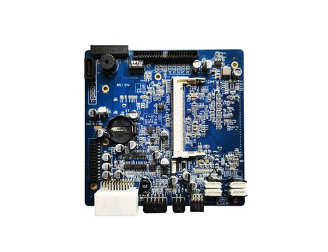
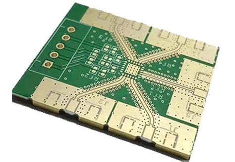
The primary material is the printed circuit board (PCB) itself, which serves as the foundation for the entire project. PCBs are typically made from fiberglass-reinforced epoxy laminate with copper traces that form the electrical pathways. Depending on the complexity of the circuit, PCBs can be single-sided, double-sided, or multi-layered.
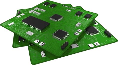
Electronic components are the next critical materials. These include resistors, capacitors, diodes, transistors, and integrated circuits, each serving a specific function within the circuit. It is essential to select components that match the specifications of the circuit design to ensure proper operation.
Additionally, flux is an often-overlooked material that plays a significant role in the soldering process. Flux cleans and prepares the surfaces to be soldered, promoting better adhesion and reducing the likelihood of cold joints. It is available in various forms, including liquid, paste, and pen applicators.
Lastly, safety equipment should not be neglected. Safety glasses protect the eyes from solder splashes and fumes, while a fume extractor or a well-ventilated workspace minimizes inhalation of potentially harmful solder fumes.
In conclusion, building a circuit board requires a comprehensive set of tools and materials to achieve a successful outcome. By ensuring that all essential items are on hand before starting the project, one can work more efficiently and effectively, ultimately leading to a well-functioning circuit board.
Step-By-Step Guide To Designing Your Own Circuit Board
Designing your own circuit board can be a rewarding and educational experience, allowing you to bring your electronic projects to life with precision and customization.
To begin, it is essential to have a clear understanding of the project requirements and the components you will be using.
Start by sketching a schematic diagram, which serves as a blueprint for your circuit. This diagram should include all the components, such as resistors, capacitors, and integrated circuits, along with their connections. Utilizing schematic capture software can streamline this process, ensuring accuracy and ease of modification.
Once the schematic is complete, the next step is to translate it into a physical layout.
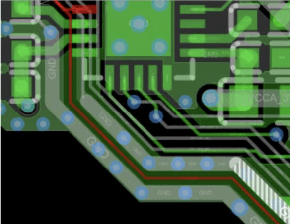
This involves arranging the components on a virtual board and routing the electrical connections between them. It is crucial to consider the placement of each component to minimize signal interference and ensure efficient use of space. Software tools like PCB design software can be invaluable at this stage, offering features such as auto-routing and design rule checks to help optimize the layout.
After finalizing the layout, it is time to generate the necessary files for manufacturing.
These files, typically in Gerber format, contain detailed information about the board’s layers, including the copper traces, solder mask, and silkscreen. It is advisable to review these files thoroughly to catch any potential errors before sending them to a manufacturer. Many PCB design software packages include built-in tools for this purpose, allowing you to visualize each layer and verify the design’s integrity.
With the Gerber files ready, the next step is to choose a PCB manufacturer.
There are numerous options available, ranging from local providers to international companies. When selecting a manufacturer, consider factors such as cost, turnaround time, and the quality of their products. It is also beneficial to read reviews and seek recommendations from other electronics enthusiasts to ensure a reliable and satisfactory experience.
Once the boards are manufactured and delivered, the assembly process begins. This involves soldering the components onto the board, which can be done manually or with the help of automated equipment. For beginners, manual soldering is often the preferred method, as it allows for greater control and understanding of the process. Ensure that you have the necessary tools, such as a soldering iron, solder, and flux, and take the time to practice on scrap boards if you are new to soldering.
After assembling the board, it is essential to test the circuit to verify its functionality. This can be done using a multimeter to check for continuity and correct voltage levels at various points in the circuit. Additionally, powering up the board and observing its behavior can help identify any issues that need to be addressed. If problems arise, refer back to the schematic and layout to troubleshoot and make necessary adjustments.
In conclusion, designing your own circuit board involves a series of methodical steps, from creating a schematic to assembling and testing the final product. By following this guide and utilizing the appropriate tools and resources, you can successfully bring your electronic projects to fruition. The process not only enhances your technical skills but also provides a deeper understanding of the intricacies of electronic design.
Common Mistakes To Avoid When Building A Circuit Board
Building a circuit board can be a rewarding endeavor, but it is not without its challenges. One of the most critical aspects of this process is avoiding common mistakes that can lead to malfunctioning circuits or even complete project failure. Understanding these pitfalls and how to steer clear of them is essential for both novice and experienced electronics enthusiasts.
Firstly, improper component placement is a frequent error that can cause significant issues.
Ensuring that each component is correctly oriented and placed in its designated spot on the board is crucial. Misplacing components can lead to short circuits or incorrect connections, which can be difficult to diagnose and rectify. To avoid this, always double-check the component layout against the schematic before soldering.
Transitioning to another common mistake, inadequate soldering techniques can also wreak havoc on a circuit board.
Cold solder joints, where the solder does not properly adhere to the component leads and pads, can result in intermittent connections or complete disconnections. To prevent this, use a soldering iron with an appropriate temperature setting and ensure that the solder flows smoothly to form a shiny, concave joint. Additionally, avoid using excessive solder, as this can create bridges between adjacent pads, leading to short circuits.
Another critical aspect to consider is the cleanliness of the circuit board.
Contaminants such as dust, grease, or flux residues can interfere with the electrical connections and cause erratic behavior. Before starting the assembly process, clean the board thoroughly with isopropyl alcohol and a lint-free cloth. After soldering, remove any flux residues using a flux remover or additional isopropyl alcohol to ensure a clean and reliable circuit.
Moving on, incorrect power supply connections are another common pitfall.
Connecting the power supply with reversed polarity or using an incorrect voltage can damage components or the entire circuit board. Always verify the power supply specifications and double-check the connections before powering up the circuit. Using polarized connectors and clearly labeling the power supply connections can help prevent such mistakes.
Furthermore, neglecting to use decoupling capacitors can lead to unstable circuit operation.
Decoupling capacitors help filter out noise and provide a stable voltage supply to the components. Place these capacitors as close as possible to the power pins of integrated circuits and other sensitive components. Failing to do so can result in erratic behavior, especially in high-frequency circuits.
In addition, inadequate thermal management can cause components to overheat and fail.
Ensure that heat-generating components, such as voltage regulators and power transistors, have adequate heat sinks or are placed in well-ventilated areas of the board. Using thermal pads or thermal paste can also help improve heat dissipation and prolong the lifespan of the components.
Lastly, overlooking the importance of proper grounding can lead to noise issues and unreliable circuit performance. A well-designed ground plane can help minimize electromagnetic interference and provide a stable reference voltage for the entire circuit. Ensure that all ground connections are made to a common ground point and avoid creating ground loops, which can introduce noise and instability.
In conclusion, building a circuit board requires careful attention to detail and a thorough understanding of potential pitfalls. By avoiding common mistakes such as improper component placement, inadequate soldering techniques, poor cleanliness, incorrect power supply connections, neglecting decoupling capacitors, inadequate thermal management, and improper grounding, you can significantly increase the chances of creating a reliable and functional circuit board. Taking the time to meticulously plan and execute each step of the process will ultimately lead to a successful and rewarding project.
Advanced Techniques For Soldering Components On A Circuit Board
Soldering components onto a circuit board is a fundamental skill for any electronics enthusiast or professional. However, mastering advanced techniques can significantly enhance the quality and reliability of your projects. To begin with, it is essential to understand the importance of preparation. Before you even heat up your soldering iron, ensure that your workspace is clean and well-organized. A clutter-free environment minimizes the risk of accidents and allows you to focus on the task at hand. Additionally, make sure that your circuit board and components are free from dust and oils, as these can impede the soldering process.
Once your workspace is prepared, the next step is to select the appropriate soldering tools.
A high-quality soldering iron with adjustable temperature settings is crucial. Different components and solder types require different temperatures, so having the ability to fine-tune your iron can make a significant difference. Moreover, using a fine-tipped soldering iron can provide greater precision, especially when working with small or densely packed components. Alongside your soldering iron, having a good quality solder wire, flux, and a desoldering pump or wick will equip you to handle any challenges that arise.
With your tools ready, the actual soldering process can begin.
Start by applying a small amount of flux to the area where you will be soldering. Flux helps to clean the metal surfaces and improve the flow of solder, resulting in stronger and more reliable joints. When heating the joint, it is crucial to apply the soldering iron to both the component lead and the pad on the circuit board simultaneously.
This ensures that both surfaces reach the appropriate temperature for the solder to flow and form a good connection. Be mindful not to overheat the components, as excessive heat can damage them.
As you proceed, it is important to maintain a steady hand and apply the solder wire to the joint, not the soldering iron.
This technique allows the solder to flow naturally into the joint, creating a smooth and shiny finish. If the solder forms a dull or grainy appearance, it may indicate a cold joint, which is prone to failure. In such cases, reheat the joint and apply a small amount of additional solder to ensure a proper connection.
Advanced soldering also involves the ability to troubleshoot and correct mistakes.
If you encounter a solder bridge, where excess solder creates an unintended connection between adjacent pads, use a desoldering pump or wick to remove the excess solder. This step is crucial for preventing short circuits and ensuring the functionality of your circuit board.
Additionally, if you need to replace a component, desoldering techniques become invaluable.
Carefully heat the joint and use a desoldering pump to remove the solder, allowing you to safely extract the component without damaging the board.
Finally, after completing the soldering process, it is essential to inspect your work thoroughly.
Use a magnifying glass or microscope to examine each joint for proper solder flow and to ensure there are no unintended connections. Testing the circuit with a multimeter can also help verify that all connections are sound and that the circuit functions as intended.
In conclusion, mastering advanced soldering techniques requires practice, patience, and attention to detail. By preparing your workspace, selecting the right tools, applying proper soldering methods, and being adept at troubleshooting, you can achieve high-quality results in your electronic projects. These skills not only enhance the reliability of your circuits but also contribute to your growth as a proficient and confident electronics enthusiast or professional.