Challenges and Solutions in PCB Material Selection for Wide Temperature Applications
Abstract
Printed Circuit Board (PCB) materials face significant challenges when operating across wide temperature ranges, particularly in aerospace, automotive, and industrial applications. This paper examines the thermal performance requirements for PCB substrates, analyzing material properties, failure mechanisms, and design considerations for reliable operation across extended temperature ranges (-55°C to 200°C+). We evaluate conventional FR-4 alternatives, high-performance laminates, and emerging material technologies that address thermal expansion, dielectric stability, and mechanical integrity challenges in extreme environments.
1. Introduction
The proliferation of electronics in harsh environments has created growing demand for PCB materials capable of reliable performance across wide temperature ranges. Traditional FR-4 epoxy substrates, while cost-effective for commercial applications, exhibit significant limitations when subjected to temperatures beyond their standard operating range (typically 0°C to 130°C). Military, aerospace, downhole drilling, and automotive applications frequently require operation from -55°C to 150°C or higher, with some specialized applications demanding performance up to 250°C.
Wide-temperature PCB materials must maintain:
- Dimensional stability across thermal cycles
- Consistent dielectric properties
- Adequate mechanical strength
- Reliable conductor adhesion
- Minimal outgassing in vacuum environments
This paper examines the material science behind these requirements and evaluates current solutions for wide-temperature PCB applications.
2. Material Properties at Temperature Extremes
2.1 Thermal Expansion Characteristics
The coefficient of thermal expansion (CTE) mismatch between copper conductors (17 ppm/°C) and substrate materials creates significant mechanical stress during temperature cycling. Conventional FR-4 exhibits a Z-axis CTE of 50-70 ppm/°C above its glass transition temperature (Tg ≈ 130°C), leading to plated through-hole (PTH) reliability issues.
High-performance alternatives employ several strategies:
- Low-CTE Fillers: Silica-filled polyimides reduce CTE to 12-20 ppm/°C
- Reinforcement Optimization: Quartz or aramid fiber reinforcements provide better CTE matching
- Multi-stage Tg Materials: Resin systems with multiple transition points distribute thermal stress
2.2 Dielectric Stability
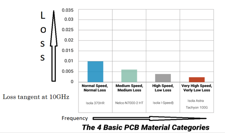
Dielectric constant (Dk) and loss tangent (Df) variations with temperature affect signal integrity, particularly in high-frequency applications. Common trends include:
| Material | Dk Variation (%/°C) | Df Variation (%/°C) |
|---|---|---|
| FR-4 | 0.15-0.25 | 2.0-4.0 |
| Polyimide | 0.05-0.10 | 1.0-1.5 |
| PTFE | 0.03-0.05 | 0.5-1.0 |
High-temperature stable ceramics in advanced composites can reduce these variations below 0.01%/°C.
2.3 Mechanical Property Degradation
Polymer-based materials experience several degradation mechanisms at elevated temperatures:
- Chain Scission: Molecular breakdown above thermal limits
- Oxidative Crosslinking: Brittleness development in air environments
- Plasticizer Loss: Increased modulus and reduced toughness
Materials with higher aromatic content (polyimides, BT epoxies) demonstrate superior retention of flexural strength at temperature extremes.
3. Material Class Comparison
3.1 High-Tg FR-4 Variants
Modified epoxy systems achieve Tg values up to 180°C through:
- Multifunctional epoxy resins
- Phenolic or cyanate ester blends
- Toughening additives
While cost-effective, these still suffer from:
- Limited thermal decomposition resistance (>200°C)
- Higher moisture absorption than advanced materials
- Significant CTE shift above Tg
3.2 Polyimide-Based Materials
Polyimides represent the workhorse of high-temperature electronics with:
- Continuous operation up to 250°C
- Tg > 260°C for most formulations
- Excellent chemical resistance
Challenges include:
- High material cost (3-5× FR-4)
- Difficult drilling and machining characteristics
- Potential for microvoid formation during lamination
3.3 Ceramic-Filled PTFE Composites
For RF/microwave applications requiring wide-temperature stability:
- Dk stability ±0.02 from -55°C to 200°C
- Ultra-low loss (Df < 0.001 at 10 GHz)
- CTE tunable through filler loading
Limitations involve:
- Poor mechanical strength for multilayer boards
- Specialized processing requirements
- High expansion above 300°C
3.4 Emerging Material Technologies
Recent developments address traditional limitations:
- Liquid Crystal Polymer (LCP): Low moisture absorption, stable CTE
- Ceramic-Polymer Nanocomposites: Tailorable thermal/electrical properties
- PEEK-Based Materials: Chemical resistance with 280°C capability
4. Design Considerations for Wide-Temperature PCBs
4.1 Layer Stackup Configuration
Asymmetric stackups exacerbate warpage during thermal cycling. Best practices include:
- Balanced copper distribution
- Symmetric prepreg/core arrangement
- Graduated material transitions in hybrid constructions
4.2 Via Reliability Enhancements
Thermal cycling induces via barrel cracks due to CTE mismatch. Mitigation strategies:
- Low-CTE dielectric materials
- Increased via annular rings
- Filled via technologies
- Hourglass via profiles for stress relief
4.3 Conductor Design
Narrow traces experience higher current density at cold temperatures where resistivity increases. Design rules should account for:
- Temperature-dependent current carrying capacity
- Thermally-induced stress concentrations at bends
- Pad cratering resistance for BGA attachments
5. Testing and Qualification
Industry standards for wide-temperature PCBs include:
- IPC-6012 Class 3 (high reliability)
- MIL-PRF-31032 (military applications)
- NASA outgassing requirements (ASTM E595)
Critical testing protocols:
- Thermal cycling (-55°C to 150°C, 1000+ cycles)
- Interconnect stress test (IST)
- High-temperature bias humidity testing
- Time-domain reflectometry (TDR) for impedance stability
6. Application-Specific Solutions
6.1 Aerospace Electronics
Space applications demand:
- Vacuum-compatible materials (low outgassing)
- Radiation resistance
- Thermal cycling performance (LEO ≈ 16 cycles/day)
Material solutions often combine polyimide substrates with specialized coatings.
6.2 Automotive Underhood
Engine compartment requirements:
- 150°C continuous with 200°C peaks
- Fluid resistance (oil, coolant, cleaners)
- Vibration endurance
Ceramic-filled hydrocarbon materials gain adoption alongside high-Tg epoxies.
6.3 Downhole Electronics
Oil/gas drilling presents extreme conditions:
- 200-250°C ambient temperatures
- High pressure (30,000 psi+)
- Shock/vibration loads
PEEK-based laminates or ceramic substrates provide necessary performance.
7. Future Trends
Material development focuses on:
- Nanocomposites with graphene/CNT reinforcement
- Self-healing dielectric materials
- Additive manufacturing of high-temperature substrates
- Embedded component technologies for reduced thermal stress
8. Conclusion
PCB materials for wide-temperature operation require careful evaluation of thermal, mechanical, and electrical property tradeoffs. While no universal solution exists, modern material systems address most application requirements through tailored formulations and proper design practices. Continued innovation in polymer science and composite technology promises further improvements in temperature capability and reliability.