Circuit board debugging method
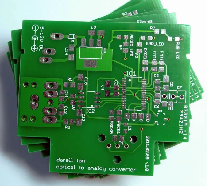
For the new PCB board that has just been brought back, we must first roughly observe whether there are any problems on the board, such as whether there are obvious cracks, short circuits, open circuits, etc. If necessary, you can check whether the resistance between the power supply and the ground wire is large enough.
For a newly designed circuit board, debugging often encounters some difficulties, especially when the board is relatively large and there are many components, it is often difficult to start. But if you master a set of reasonable debugging methods, debugging will be twice the result with half the effort.
Circuit board debugging step 1:
For the new PCB board that has just been brought back, we must first roughly observe whether there are any problems on the board, such as whether there are obvious cracks, short circuits, open circuits, etc. If necessary, you can check whether the resistance between the power supply and the ground wire is large enough.
Circuit board debugging step 2:
Then it is time to install the components. For independent modules, if you are not sure that they are working properly, it is best not to install them all, but install them one by one (for smaller circuits, they can be installed all at once), so that it is easy to determine the scope of the fault, so as to avoid being unable to start when encountering problems.
Generally speaking, you can install the power supply first, and then power on to check whether the power output voltage is normal. If you are not very sure when powering on (even if you are very sure, it is recommended that you add a fuse just in case), you can consider using an adjustable regulated power supply with current limiting function.
Preset the overcurrent protection current first, then slowly increase the voltage value of the regulated power supply, and monitor the input current, input voltage and output voltage. If there are no problems such as overcurrent protection during the upward adjustment, and the output voltage is also normal, it means that the power supply is OK. Otherwise, disconnect the power supply, find the fault point, and repeat the above steps until the power supply is normal.
Step 3 of circuit board debugging:
Next, gradually install other modules. After each module is installed, power it on for testing. When powering on, follow the above steps to avoid overcurrent and burn components due to design errors or/and installation errors.
There are generally the following ways to find faults:
① Voltage measurement method. First, check whether the voltage of each chip power pin is normal, then check whether various reference voltages are normal, and whether the working voltage of each point is normal. For example, when a general silicon triode is turned on, the BE junction voltage is about 0.7V, while the CE junction voltage is about 0.3V or less. If the BE junction voltage of a triode is greater than 0.7V (except for special triodes, such as Darlington tubes, etc.), it may be that the BE junction is open.
②Signal injection method. Add the signal source to the input end, and then measure the waveform of each point in turn to see if it is normal to find the fault point. Sometimes we also use simpler methods, such as holding a pair of tweezers in hand, touch the input end of each level, and see if there is a response at the output end. This is often used in audio, video and other amplifier circuits (but be aware that this method cannot be used for circuits with hot bottom plates or high voltage circuits, otherwise it may cause electric shock). If there is no response when touching the previous level, but there is a response when touching the next level, it means that the problem is in the previous level, and it should be checked in detail.
③ Of course, there are many other ways to find the fault point, such as looking, listening, smelling, touching, etc. “Looking” means to see if the component has obvious mechanical damage, such as cracking, burning, deformation, etc.; “Listening” means to listen to whether the working sound is normal, such as some things that should not be ringing are ringing, the places that should be ringing are not ringing or the sound is abnormal, etc.; “Smelling” means to check whether there is any odor, such as the smell of burning, the smell of capacitor electrolyte, etc. For an experienced electronic maintenance personnel, these odors are very sensitive; “Touching” means to use your hands to test whether the temperature of the device is normal, such as too hot or too cold. Some power devices will heat up when working. If they feel cool to the touch, it can basically be judged that it is not working. But if the place that should not be hot is hot or the place that should be hot is too hot, it is not okay. For general power transistors, voltage regulator chips, etc., it is completely fine to work below 70 degrees. What is the concept of 70 degrees? If you can hold your hand for more than three seconds, it means the temperature is probably below 70 degrees (note to touch it tentatively first to avoid burning your hand).