Circuit Symbol for Potentiometer: A Comprehensive Guide
Introduction
A potentiometer is a widely used variable resistor in electronic circuits, allowing for adjustable voltage division and resistance control. Understanding its circuit symbol is essential for reading schematics and designing circuits. This article explores the circuit symbol for a potentiometer, its variations, functionality, and applications in electronics.
1. What is a Potentiometer?
A potentiometer (often called a “pot”) is a three-terminal resistor with an adjustable sliding or rotating contact that forms an adjustable voltage divider. It is commonly used for:
- Volume control in audio devices
- Brightness adjustment in displays
- Calibration in electronic circuits
- Position sensing in robotics
Potentiometers come in different types, including:
- Rotary potentiometers (knob-adjustable)
- Linear potentiometers (slider-adjustable)
- Trimmer potentiometers (small, screw-adjustable for calibration)
2. Standard Circuit Symbol for a Potentiometer
The circuit symbol for a potentiometer varies slightly depending on the standard used (IEEE, IEC, or ANSI), but the most common representation is:
2.1 Basic Symbol (IEC Standard)
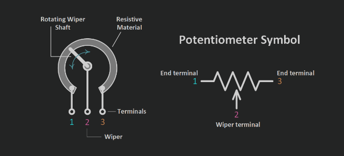
The International Electrotechnical Commission (IEC) symbol consists of:
- A resistor symbol (a rectangle) with an arrow pointing diagonally across it.
- Three terminals:
- Two fixed ends (terminals 1 and 3)
- One wiper (terminal 2, the middle terminal)
Terminal 1 ----/\/\/\/\---- Terminal 3
               |
             Terminal 2 (Wiper)
2.2 ANSI/IEEE Standard
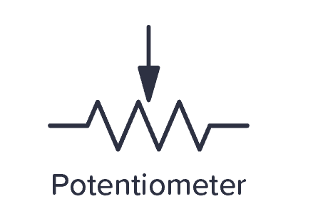
The American National Standards Institute (ANSI) and Institute of Electrical and Electronics Engineers (IEEE) use a zigzag resistor symbol with an arrow representing the wiper:
Terminal 1 ~~~/\~~~/\~~~ Terminal 3
                |
              Terminal 2 (Wiper)
2.3 Variations in Symbols
- Rheostat Mode: If only two terminals are used (one fixed end and the wiper), the symbol may resemble a variable resistor.
- Digital Potentiometer: Some schematics use a digital pot symbol with additional control pins (e.g., up/down or SPI interface).
3. How a Potentiometer Works in a Circuit
The potentiometer acts as a voltage divider when connected to a circuit:
- Fixed Resistance: The total resistance between terminals 1 and 3 remains constant.
- Adjustable Output: The wiper (terminal 2) moves along the resistive element, changing the resistance ratio between terminals 1-2 and 2-3.
- Voltage Division: If a voltage is applied across terminals 1 and 3, the output voltage at terminal 2 varies based on the wiper’s position.
Example Circuit: Voltage Divider
Vin ----[Potentiometer]---- GND
          |
Vout (Wiper)- When the wiper is at the midpoint, Vout = Vin / 2.
- Moving the wiper changes Vout proportionally.
4. Different Types of Potentiometers and Their Symbols
4.1 Rotary Potentiometer
- Used in knobs (e.g., volume control).
- Symbol: Resistor with an arched arrow indicating rotation.
4.2 Linear Potentiometer
- Used in sliders (e.g., light dimmers).
- Symbol: Resistor with a straight arrow indicating linear motion.
4.3 Trimmer Potentiometer
- Used for calibration (e.g., tuning circuits).
- Symbol: Resistor with a small screwdriver-adjustable arrow.
4.4 Digital Potentiometer
- Electronically controlled (via I²C, SPI).
- Symbol: Standard pot symbol with digital control lines.
5. Common Applications in Circuits
- Volume Control: Adjusting audio levels in amplifiers.
- Brightness Adjustment: Controlling LED or LCD backlight intensity.
- Sensor Calibration: Fine-tuning sensor outputs.
- User Input Devices: Joysticks, dials, and sliders in control panels.
6. Reading Potentiometer Symbols in Schematics
When analyzing a circuit diagram:
- Identify the three terminals.
- Determine if it’s a voltage divider or variable resistor configuration.
- Check for additional markings (e.g., logarithmic vs. linear taper).
7. Troubleshooting Potentiometer Circuits
Common issues include:
- Poor Contact: Dirty or worn-out wiper causing erratic output.
- Open Circuit: Broken resistive track.
- Incorrect Wiring: Misplaced wiper or fixed terminals.
8. Conclusion
The circuit symbol for a potentiometer is a fundamental representation in electronics, indicating its role as a variable resistor or voltage divider. Understanding its variations helps in designing and troubleshooting circuits effectively. Whether used in audio controls, calibration, or sensor adjustments, potentiometers remain a crucial component in modern electronics.
By mastering the potentiometer’s symbol and functionality, engineers and hobbyists can better utilize this versatile component in their projects.


