Common Issues in PCB Application and How to Solve Them
Introduction
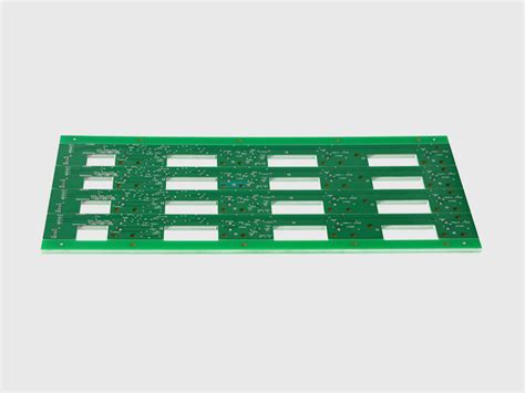
Printed Circuit Boards (PCBs) are the backbone of modern electronics, found in everything from smartphones to industrial machinery. While PCB technology has advanced significantly over the decades, engineers and technicians still encounter various challenges during design, manufacturing, and application. This article explores the most common problems encountered in PCB application, their root causes, and practical solutions to address them.
1. Soldering Problems
1.1 Cold Solder Joints
One of the most frequent issues in PCB assembly is cold solder joints, which occur when the solder doesn’t melt properly, creating a weak connection. These joints often appear dull, lumpy, or cracked rather than smooth and shiny.
Causes:
- Insufficient heat during soldering
- Contaminated solder or pads
- Movement during cooling
- Wrong solder alloy composition
Solutions:
- Ensure proper temperature control (typically 300-350°C for lead-based solder)
- Clean PCB pads before soldering
- Use appropriate flux
- Allow joints to cool undisturbed
- Implement visual inspection or automated optical inspection (AOI)
1.2 Solder Bridging
Solder bridging happens when solder accidentally connects two or more adjacent pins that should not be electrically connected.
Causes:
- Excessive solder application
- Incorrect stencil design
- Improper component placement
- Inadequate solder mask between pads
Solutions:
- Optimize solder paste volume through stencil design
- Ensure proper component placement accuracy
- Use appropriate solder mask between fine-pitch components
- Implement rework procedures using solder wick or vacuum tools
2. Component Issues
2.1 Tombstoning
Tombstoning occurs when a surface-mount component stands up on one end during reflow soldering, creating an open circuit.
Causes:
- Uneven heating of component terminals
- Imbalanced pad sizes
- Incorrect solder paste deposition
- Component size mismatch with pads
Solutions:
- Design symmetrical pad layouts
- Ensure even thermal mass distribution
- Control reflow profile carefully
- Use appropriate solder paste volume
2.2 Component Misalignment
Misaligned components can lead to poor connections or short circuits.
Causes:
- Placement machine inaccuracy
- Incorrect footprint design
- Solder paste slump before reflow
- Board warpage during processing
Solutions:
- Calibrate pick-and-place machines regularly
- Verify component footprints in CAD libraries
- Optimize solder paste rheology
- Use proper board support during reflow
3. PCB Design Flaws
3.1 Insufficient Clearance and Creepage
Inadequate spacing between conductors can lead to short circuits or reduced product lifespan.
Causes:
- Violation of design rules
- Overestimation of PCB manufacturing capabilities
- Ignoring high-voltage requirements
- Last-minute design changes
Solutions:
- Adhere to IPC standards for spacing
- Consider voltage requirements early in design
- Use design rule checking (DRC) tools
- Consult with PCB manufacturer about capabilities
3.2 Poor Thermal Management
Overheating components can lead to premature failure.
Causes:
- Inadequate copper pour for heat dissipation
- Lack of thermal vias under hot components
- Poor component placement creating hot spots
- Insufficient board ventilation
Solutions:
- Implement thermal relief connections
- Use thermal vias for heat transfer
- Consider heat sinks or forced air cooling
- Perform thermal simulation during design
4. Manufacturing Defects
4.1 Copper Trace Damage
Broken or compromised traces can cause open circuits.
Causes:
- Mechanical stress during handling
- Over-etching during fabrication
- Voids in plating
- Delamination due to moisture
Solutions:
- Specify appropriate copper weight
- Implement proper handling procedures
- Control etching process parameters
- Bake boards before assembly if moisture-sensitive
4.2 Plating Voids in Vias
Voids in via plating can create unreliable interlayer connections.
Causes:
- Poor plating bath chemistry
- Inadequate cleaning before plating
- Air bubbles trapped in vias
- Improper drilling parameters
Solutions:
- Optimize plating process parameters
- Implement proper via cleaning
- Consider via fill options for critical connections
- Specify tented vias where appropriate
5. Environmental and Operational Issues
5.1 Electrochemical Migration
Metal migration can create conductive paths between traces, causing short circuits.
Causes:
- Moisture contamination
- Ionic contamination on board surface
- DC bias between conductors
- Lack of conformal coating in humid environments
Solutions:
- Implement proper cleaning after assembly
- Apply conformal coating for harsh environments
- Design with sufficient spacing in humid applications
- Use no-clean fluxes properly
5.2 Mechanical Stress Failures
Physical stress can damage components and connections.
Causes:
- Board flexure in operation
- Vibration in application
- Improper mounting
- Thermal expansion mismatch
Solutions:
- Add stiffeners where needed
- Use strain relief for connectors
- Consider flexible PCBs for dynamic applications
- Optimize component placement to reduce stress

6. Signal Integrity Problems
6.1 Electromagnetic Interference (EMI)
Unwanted radiation or susceptibility can affect performance.
Causes:
- Poor grounding strategy
- Inadequate shielding
- Long parallel trace runs
- High-speed signals without proper termination
Solutions:
- Implement solid ground planes
- Use proper trace routing techniques
- Add shielding where needed
- Consider EMI filters for sensitive circuits
6.2 Crosstalk
Unwanted signal coupling between adjacent traces.
Causes:
- Parallel trace runs that are too long
- Inadequate spacing between signals
- Lack of ground shielding between traces
- High-impedance circuits near noisy signals
Solutions:
- Increase spacing between critical traces
- Implement ground guards between sensitive signals
- Reduce parallel run lengths
- Use differential signaling for sensitive analog circuits
7. Power Integrity Issues
7.1 Voltage Drops
Excessive voltage drop can lead to circuit malfunction.
Causes:
- Undersized power traces
- Inadequate decoupling
- High current paths with excessive length
- Poor via placement in power distribution
Solutions:
- Calculate proper trace widths for current
- Implement power planes where needed
- Place decoupling capacitors properly
- Use multiple vias for high-current connections
7.2 Ground Bounce
Switching noise in ground connections can affect signal integrity.
Causes:
- High-speed switching with inadequate return paths
- Inductance in ground connections
- Poor component placement
- Insufficient ground vias
Solutions:
- Implement solid ground planes
- Use multiple ground vias for ICs
- Place decoupling capacitors close to ICs
- Consider split ground planes carefully
8. Testing and Debugging Challenges
8.1 Limited Test Access
Difficulty accessing test points complicates debugging.
Causes:
- Lack of test points in design
- Components covering test locations
- High-density designs leaving no room for probes
Solutions:
- Include dedicated test points in design
- Consider test point spacing requirements
- Use vias as test points where appropriate
- Plan for bed-of-nails fixture access
8.2 Intermittent Failures
Problems that appear inconsistently are particularly challenging.
Causes:
- Marginal connections
- Temperature-sensitive components
- Mechanical stress factors
- Environmental factors like humidity
Solutions:
- Implement rigorous environmental testing
- Use strain relief for suspect connections
- Consider vibration testing
- Apply thermal imaging for heat-related issues
Conclusion
PCB application involves numerous potential pitfalls from design through manufacturing to field operation. By understanding these common issues—including soldering problems, component issues, design flaws, manufacturing defects, environmental factors, signal integrity challenges, power integrity concerns, and testing difficulties—engineers can implement preventive measures during the design phase and corrective actions when problems arise.
The key to successful PCB application lies in:
- Thorough design review and simulation
- Careful selection of materials and components
- Collaboration with manufacturing partners
- Comprehensive testing protocols
- Continuous learning from past issues
As PCB technology continues to evolve with higher densities, faster signals, and more challenging operating environments, staying informed about potential problems and their solutions becomes increasingly important for electronics professionals. By addressing these common issues systematically, organizations can improve product reliability, reduce time-to-market, and enhance overall product quality.