Common Quality Issues in PCB Solder Mask Process and Their Solutions
Abstract
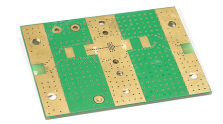
The solder mask process is a critical step in printed circuit board (PCB) manufacturing, providing insulation, protection against oxidation, and preventing solder bridges. However, various quality issues may arise during this process, affecting PCB reliability and performance. This paper explores common solder mask defects, their root causes, and effective solutions to improve yield and product quality.
1. Introduction
The solder mask (or solder resist) is a thin polymer layer applied to PCBs to protect copper traces from oxidation, prevent solder bridging, and enhance electrical insulation. Despite advancements in materials and application techniques, defects such as poor adhesion, uneven coating, pinholes, and discoloration still occur. Addressing these issues requires a thorough understanding of the solder mask process, material properties, and environmental conditions.

2. Common Solder Mask Quality Issues and Solutions
2.1 Poor Adhesion
Symptoms:
- Solder mask peeling off during assembly or handling
- Blistering or bubbling after thermal exposure
Root Causes:
- Contaminated copper surface (oxides, fingerprints, or residues)
- Impropre surface preparation (inadequate cleaning or micro-etching)
- Incorrect solder mask curing conditions (undercuring or overcuring)
Solutions:
- Ensure thorough cleaning using chemical cleaners and micro-etching
- Implement plasma treatment for better surface adhesion
- Optimize curing temperature and time according to the solder mask specifications
2.2 Solder Mask Voids/Pinholes
Symptoms:
- Tiny holes or gaps in the solder mask layer
- Exposed copper traces leading to potential short circuits
Root Causes:
- Air bubbles trapped during solder mask application
- Contaminated solder mask material or improper mixing
- Dust or debris on the PCB surface before coating
Solutions:
- Use vacuum degassing to remove air bubbles from the solder mask
- Ensure a cleanroom environment during application
- Apply multiple thin layers instead of a single thick coating
2.3 Uneven Coating or Thickness Variation
Symptoms:
- Inconsistent solder mask thickness across the PCB
- Poor coverage in certain areas (e.g., near high-density traces)
Root Causes:
- Uneven spray coating or curtain coating application
- Viscosity issues with the solder mask material
- Impropre drying or pre-baking conditions
Solutions:
- Calibrate coating equipment for uniform application
- Adjust solder mask viscosity with recommended thinners
- Optimize pre-bake time and temperature to prevent sagging
2.4 Misregistration (Alignment Issues)
Symptoms:
- Solder mask misaligned with underlying copper pads
- Mask encroachment on solderable areas
Root Causes:
- Poor artwork alignment during exposure
- PCB panel warping or stretching
- Inaccurate exposure equipment calibration
Solutions:
- Use high-precision optical alignment systems
- Implement panel support fixtures to minimize warpage
- Regularly calibrate exposure machines
2.5 Discoloration or Yellowing
Symptoms:
- Solder mask turning yellow or brown after curing
- Reduced UV resistance and aesthetic defects
Root Causes:
- Overcuring or excessive UV exposure
- Low-quality solder mask material
- Contamination from flux or cleaning agents
Solutions:
- Follow recommended curing parameters strictly
- Use high-temperature-resistant solder mask formulations
- Ensure proper post-curing cleaning
2.6 Solder Mask Cracking
Symptoms:
- Fine cracks appearing after thermal cycling or mechanical stress
- Reduced protection against moisture and chemicals
Root Causes:
- Excessive mechanical stress during depaneling
- Thermal expansion mismatch between solder mask and substrate
- Brittle solder mask formulation
Solutions:
- Optimize depaneling methods (laser cutting, routing)
- Use flexible solder mask materials for high-stress applications
- Implement post-curing stress relief processes
2.7 Incomplete Development
Symptoms:
- Residual solder mask in unwanted areas
- Poor definition of openings for soldering
Root Causes:
- Insufficient developing time or solution concentration
- Overexposure or underexposure in UV curing
- Aged or contaminated developer solution
Solutions:
- Monitor and refresh developer solution regularly
- Optimize exposure energy and development time
- Use high-resolution artwork films
3. Process Optimization Strategies
3.1 Material Selection
- Choose solder mask materials compatible with PCB substrate and assembly processes (e.g., lead-free soldering).
- Evaluate thermal, mechanical, and chemical resistance properties.
3.2 Process Control
- Implement real-time monitoring of coating thickness and curing conditions.
- Maintain strict environmental controls (temperature, humidity, and cleanliness).
3.3 Equipment Maintenance
- Regularly clean and calibrate coating, exposure, and developing machines.
- Replace worn-out parts to ensure consistent performance.
3.4 Operator Training
- Train personnel in proper handling, inspection, and troubleshooting techniques.
- Establish standard operating procedures (SOPs) for each process step.
4. Conclusion
Solder mask defects can significantly impact PCB functionality and reliability. By identifying root causes and implementing corrective measures, manufacturers can reduce scrap rates and improve product quality. Continuous process optimization, material improvements, and strict quality control are essential for minimizing solder mask-related issues in PCB production.