Composition and Basic Process Operations of SMT Production Lines
Abstract
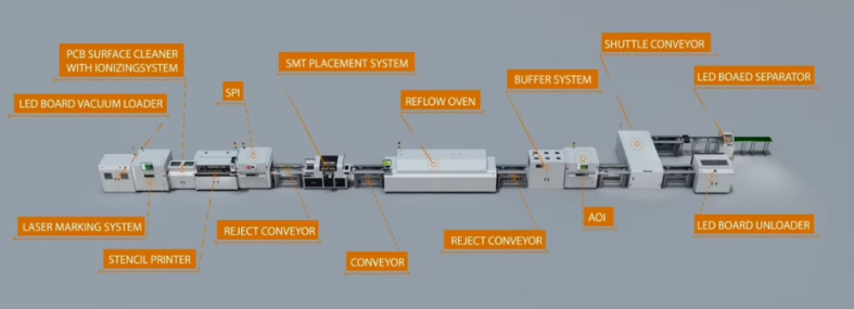
Surface Mount Technology (SMT) has become the dominant method for assembling modern electronic circuits due to its efficiency, precision, and ability to support miniaturized components. An SMT production line consists of several key processes, including solder paste printing, component placement, reflow soldering, inspection, and cleaning. This paper explores the fundamental operations of an SMT production line, detailing each stage’s role in ensuring high-quality PCB assembly.
1. Introduction
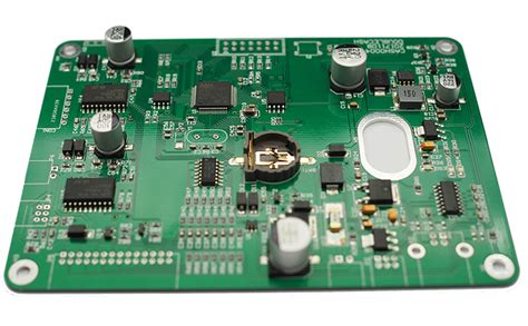
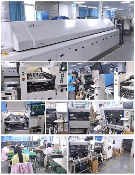
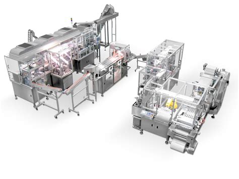
SMT is a method for constructing electronic circuits where components are mounted directly onto the surface of printed circuit boards (PCBs). Unlike through-hole technology, SMT allows for smaller components, higher component density, and automated assembly, making it essential for modern electronics manufacturing. A typical SMT production line integrates multiple automated machines to perform sequential operations with minimal human intervention.
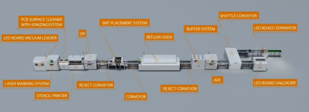
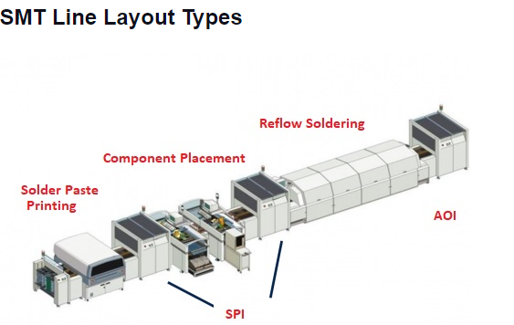
This paper examines the core processes of an SMT production line, including:
- Solder Paste Printing
- Component Placement
- Reflow Soldering
- Inspection and Quality Control
- Cleaning and Conformal Coating (if required)
2. Solder Paste Printing
The first step in the SMT process is applying solder paste to the PCB.
2.1 Stencil Preparation
A stainless steel or polyester stencil, designed with apertures matching the PCB’s pad layout, is used to deposit solder paste accurately.
2.2 Solder Paste Application
A squeegee blade spreads solder paste across the stencil, forcing it through the apertures onto the PCB pads. The paste consists of tiny solder particles suspended in flux, which helps in bonding and prevents oxidation.
2.3 Inspection (SPI – Solder Paste Inspection)
After printing, an automated Solder Paste Inspection (SPI) system checks for defects such as insufficient paste, smearing, or misalignment. Early detection prevents soldering defects in later stages.
3. Component Placement
Once solder paste is applied, the PCB moves to the pick-and-place machine.
3.1 Pick-and-Place Machine Operation
- Feeder System: Components are supplied in reels, trays, or tubes.
- Vision Alignment: Cameras ensure precise component positioning.
- Nozzle Mechanism: Vacuum nozzles pick components and place them on the solder paste.
3.2 Types of Placement Machines
- High-Speed Placers: For small, passive components (resistors, capacitors).
- Precision Placers: For fine-pitch ICs (BGAs, QFPs).
4. Reflow Soldering
After component placement, the PCB enters the reflow oven to form permanent solder joints.
4.1 Reflow Profile
The oven follows a controlled temperature profile:
- Preheat: Gradual heating to activate flux.
- Soak: Stabilizes temperature to remove paste volatiles.
- Reflow: Peak temperature melts solder (typically 220-250°C).
- Cooling: Solidifies joints to prevent defects.
4.2 Nitrogen vs. Air Environment
- Nitrogen Reflow: Reduces oxidation, improving joint quality.
- Air Reflow: More cost-effective but may lead to minor oxidation.
5. Inspection and Quality Control
Post-reflow inspection ensures reliability.
5.1 Automated Optical Inspection (AOI)
- Checks for missing/misaligned components, solder bridges, and tombstoning.
5.2 X-Ray Inspection (AXI)
- Essential for inspecting hidden joints (e.g., BGA, QFN components).
5.3 Functional Testing
- Verifies electrical performance before final assembly.
6. Cleaning and Conformal Coating (Optional)
6.1 Cleaning
- Removes flux residues using solvents or water-based cleaners.
6.2 Conformal Coating
- Protects PCBs from moisture, dust, and corrosion in harsh environments.
7. Conclusion
An SMT production line integrates multiple automated processes to achieve high-speed, high-precision PCB assembly. Key stages—solder paste printing, component placement, reflow soldering, inspection, and cleaning—ensure reliable and efficient manufacturing. As electronics continue to miniaturize, advancements in SMT technology will further enhance production capabilities.