Comprehensive Inspection Methods for PCB Soldering Departments
Introduction
Printed Circuit Board (PCB) soldering is a critical process in electronics manufacturing, ensuring reliable electrical connections between components and the board. Poor soldering can lead to defects such as cold joints, bridging, or insufficient solder, which may cause device failure. Therefore, rigorous inspection methods are essential to maintain high-quality standards in PCB assembly.
This article explores various inspection techniques used in PCB soldering departments, including visual inspection, automated optical inspection (AOI), X-ray inspection, and functional testing. Each method has its advantages and limitations, and a combination of these techniques is often employed to ensure defect-free soldering.
1. Visual Inspection
Visual inspection is the most basic yet essential method for checking soldering quality. It involves manual examination by trained inspectors or magnification tools to identify visible defects.
1.1 Manual Visual Inspection (MVI)
- Tools Used: Magnifying lenses, microscopes, or digital cameras.
- Common Defects Detected:
- Solder Bridges: Unintended connections between adjacent pads.
- Cold Joints: Dull, grainy, or cracked solder due to insufficient heat.
- Insufficient Solder: Weak or incomplete connections.
- Excessive Solder: Bulging solder that may cause short circuits.
- Advantages: Low cost, immediate feedback.
- Limitations: Human error, fatigue, and inability to detect hidden defects.
1.2 Enhanced Visual Inspection with Microscopes
For high-density PCBs with fine-pitch components, microscopes (e.g., stereo or digital microscopes) provide better accuracy.
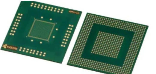
- Applications: BGA (Ball Grid Array), QFN (Quad Flat No-leads) inspection.
- Limitations: Time-consuming for large batches.
2. Automated Optical Inspection (AOI)
AOI systems use high-resolution cameras and image processing software to detect soldering defects automatically.
2.1 How AOI Works
- The system scans the PCB and compares captured images with pre-programmed standards.
- Algorithms detect anomalies such as missing components, misalignment, or solder defects.
2.2 Advantages of AOI
- High Speed: Can inspect hundreds of PCBs per hour.
- Consistency: Eliminates human bias.
- Data Logging: Stores defect records for process improvement.
2.3 Limitations
- Cannot Inspect Hidden Joints: E.g., solder joints under components like BGAs.
- False Positives/Negatives: Requires fine-tuning of detection algorithms.
3. X-Ray Inspection (AXI)
For inspecting hidden solder joints, X-ray inspection is indispensable, especially for complex assemblies like BGAs and QFNs.
3.1 How X-Ray Inspection Works
- X-rays penetrate the PCB, revealing internal structures.
- Detectors capture images showing solder ball integrity, voids, or misalignment.
3.2 Types of X-Ray Inspection
- 2D X-Ray: Provides a flat image; useful for basic defect detection.
- 3D X-Ray (Computed Tomography): Offers cross-sectional views for deeper analysis.
3.3 Advantages
- Detects Hidden Defects: Essential for BGA, CSP (Chip Scale Package).
- Quantitative Analysis: Measures void percentages in solder joints.
3.4 Limitations
- High Cost: Equipment is expensive compared to AOI.
- Safety Concerns: Requires radiation shielding.
4. Functional Testing
After visual and automated inspections, functional testing ensures the PCB operates as intended.
4.1 In-Circuit Testing (ICT)
- Uses bed-of-nails testers to check electrical connectivity.
- Detects open/short circuits, wrong component values.
4.2 Flying Probe Testing
- Movable probes test points without fixed fixtures.
- Flexible for low-volume or prototype testing.
4.3 Burn-In Testing
- Powers the PCB under stress conditions to identify early failures.
5. Combining Inspection Methods for Optimal Results
No single method can catch all defects. A multi-stage inspection approach is recommended:
- Pre-Soldering Checks: Verify component placement.
- Post-Reflow AOI: Detect surface defects.
- X-Ray for Hidden Joints: Inspect BGAs and micro-components.
- Functional Testing: Ensure operational reliability.
Conclusion
Effective PCB soldering inspection requires a combination of manual, automated, and functional testing methods. While visual inspection remains fundamental, AOI and X-ray systems enhance defect detection for modern, high-density PCBs. By integrating these techniques, manufacturers can minimize defects, improve yield, and ensure long-term reliability of electronic products.
Investing in advanced inspection technologies not only reduces rework costs but also strengthens quality assurance in PCB manufacturing.