Crystal Oscillator and PCB Mismatch: Causes, Effects, and Solutions
Introduction
Crystal oscillators (XO) are critical components in electronic circuits, providing precise clock signals for microcontrollers, processors, and communication modules. However, a common issue in PCB (Printed Circuit Board) design and manufacturing is the mismatch between the crystal oscillator and the PCB. This misalignment can lead to frequency instability, signal distortion, or complete circuit failure.
This article explores the causes, effects, and solutions for crystal oscillator and PCB mismatch, helping engineers and designers mitigate these issues effectively.
1. Causes of Crystal Oscillator and PCB Mismatch
1.1. Incorrect Footprint Design
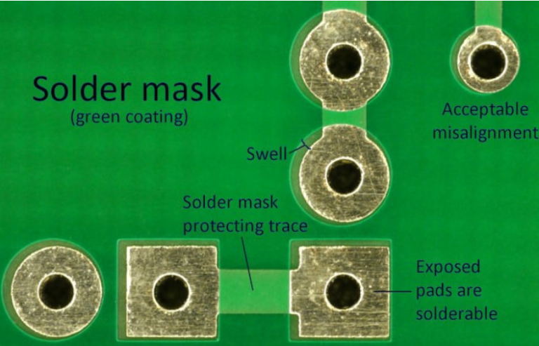
One of the most frequent causes of mismatch is an incorrect PCB footprint. If the pad dimensions, spacing, or solder mask opening do not match the crystal oscillator’s specifications, the component may not sit properly, leading to poor soldering or mechanical stress.
1.2. Soldering Issues
- Cold Solder Joints: Poor soldering can result in weak electrical connections.
- Excessive Solder: Too much solder can cause short circuits or mechanical stress.
- Misalignment During Reflow: If the crystal oscillator shifts during reflow soldering, it may not make proper contact.
1.3. Mechanical Stress and Vibration
Crystal oscillators are sensitive to mechanical stress. If the PCB undergoes bending or vibration (e.g., in automotive or industrial applications), the oscillator’s performance may degrade.
1.4. Impedance Mismatch
The PCB trace impedance must match the crystal oscillator’s load capacitance. If the traces are too long or improperly designed, signal reflections and frequency deviations can occur.
1.5. Environmental Factors
- Temperature Variations: Extreme temperatures can cause PCB expansion/contraction, affecting oscillator stability.
- Humidity and Contamination: Moisture or flux residues can alter electrical characteristics.
2. Effects of Crystal Oscillator and PCB Mismatch
2.1. Frequency Instability
A poorly matched crystal oscillator may drift from its specified frequency, leading to timing errors in digital systems.
2.2. Signal Integrity Issues
- Jitter: Unstable clock signals can introduce jitter, affecting high-speed communications.
- Harmonic Distortion: Mismatched impedance can cause unwanted harmonics.
2.3. Startup Failures
Some oscillators may fail to start if the PCB design does not provide sufficient initial excitation energy.
2.4. Increased Power Consumption
A mismatched oscillator may draw more current, reducing battery life in portable devices.
2.5. Complete Circuit Failure
In severe cases, the oscillator may stop functioning, causing the entire system to fail.
3. Solutions to Prevent and Fix Mismatch Issues
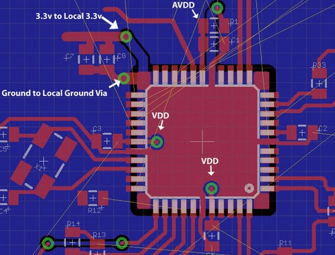
3.1. Accurate PCB Footprint Design
- Verify the oscillator’s datasheet for exact dimensions.
- Use CAD tools to ensure proper pad spacing and solder mask alignment.
3.2. Proper Soldering Techniques
- Follow recommended reflow profiles.
- Use stencil designs that prevent excessive solder paste deposition.
- Inspect solder joints under a microscope if necessary.
3.3. Mechanical Reinforcement
- Use epoxy or silicone to secure the oscillator in high-vibration environments.
- Avoid placing the oscillator near PCB flex points.
3.4. Impedance Matching and Trace Routing
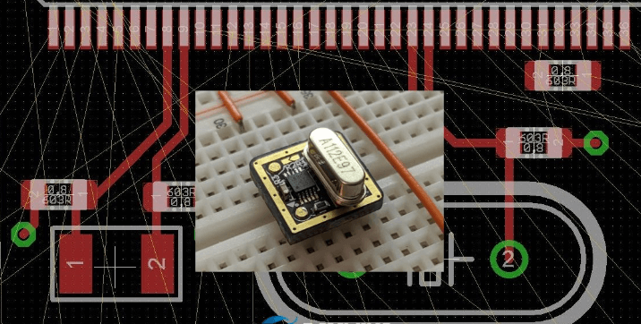
- Keep oscillator traces short and away from noisy signals.
- Match load capacitance with appropriate decoupling capacitors.
3.5. Environmental Protection
- Conformal coating can protect against humidity and contaminants.
- Select oscillators with wider temperature ranges if needed.
3.6. Testing and Validation
- Measure frequency stability with an oscilloscope or spectrum analyzer.
- Perform thermal cycling tests to ensure reliability.
4. Case Study: Common Mismatch Scenarios
4.1. Incorrect Load Capacitance
A microcontroller-based design failed because the PCB’s load capacitors (e.g., 22pF) did not match the oscillator’s requirement (12pF). Adjusting the capacitors resolved the issue.
4.2. Poor Soldering in High-Frequency Circuits
A 32.768 kHz RTC (Real-Time Clock) crystal in a wearable device had intermittent failures due to cold solder joints. Reflowing with proper temperature settings fixed the problem.
4.3. Vibration-Induced Failures in Automotive PCBs
An engine control unit (ECU) experienced clock drift due to oscillator displacement. Adding mechanical support (epoxy) improved reliability.
5. Conclusion
A mismatch between a crystal oscillator and PCB can lead to significant performance issues or complete system failure. By understanding the root causes—such as footprint errors, soldering defects, mechanical stress, and impedance mismatches—engineers can implement preventive measures. Proper design validation, soldering techniques, and environmental protection are key to ensuring stable oscillator performance.
For mission-critical applications, rigorous testing and compliance with manufacturer guidelines are essential. By addressing these factors, designers can enhance PCB reliability and avoid costly rework.